
6
TM 5-3805-293-23-3
FIELD MAINTENANCE
-
CLUTCH MODULATING VALVES REPLACEMENT
0
155
Removal, Cleaning and Inspection, Installation
INITIAL SETUP
References
Tools and Special Tools
0
0
Tool Kit, General Mechanic's
WP 0346
0
(WP 0354, Item 83)
0
Equipment Condition
0
Pan, Drain (S0255) (WP 0354, Item 85)
0
Machine parked (TM 5-3805-293-10)
0
Materials/Parts
Transmission oil drained (WP 0128)
0
0
Oil, Lubricating OE/HDO-30
Drawings Required
(WP 0355, Item 21)
0
0
TM 5-3805-293-24P, Figure 79
Rag, Wiping (WP 0355, Item 25)
0
0
Strap, Tiedown, Electrical Component
Estimated Time to Complete
0
(WP 0355, Item 33)
0
2.0 Hr
0
O-ring
0
Seal
0
N OT E
All eight clutch modulating valve replacement procedures are identical. Procedure for
modulating valve clutch 8 is shown.
Remove clips and tiedown straps as required.
REMOVAL
000155
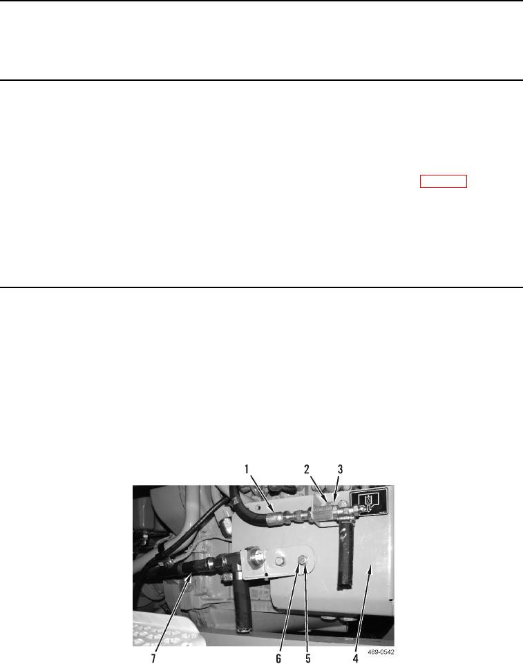
1. Remove two bolts (Figure 1, Item 2), washers (Figure 1, Item 3), and hose assembly (Figure 1, Item 1) from
cover (Figure 1, Item 4). Position hose assembly aside.
2. Remove two bolts (Figure 1, Item 5), washers (Figure 1, Item 6), and hose assembly (Figure 1, Item 7) from
cover (Figure 1, Item 4). Position hose assembly aside.
Figure 1. Hose Assemblies.
0155