
TM 5-3805-293-23-3
0154
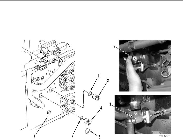
REMOVAL CONTINUED
3. Remove snapring (Figure 3, Item 5), and use yoke and jaw from universal puller kit (Figure 3, Item 3) to
remove lubrication relief valve (Figure 3, Item 4), and O-ring (Figure 3, Item 6) from transmission (Figure 3,
Item 7). Discard O-ring.
4. Use yoke and jaw from universal puller kit (Figure 3, Item 3) to remove transmission oil cooler relief valve
(Figure 3, Item 2) and O-ring (Figure 3, Item 1) from transmission (Figure 3, Item 7). Discard O-ring.
Figure 3. Transmission Oil Cooler Relief Valve.
0154
END OF TASK
CLEANING AND INSPECTION
000154
Clean and inspect all mechanical parts IAW Mechanical General Maintenance Instructions (WP 0346).
END OF TASK