
TM 5-3805-293-23-3
0099
INSTALLATION CONTINUED
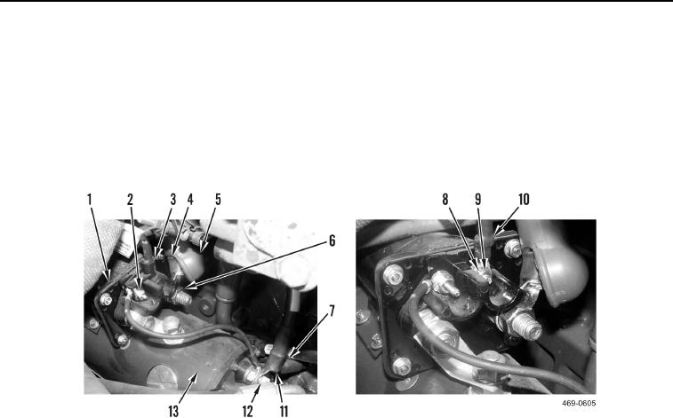
7. Install two negative cables (Figure 7, Item 7), nut (Figure 7, Item 12), and protective boot (Figure 7, Item 11) on
starter motor (Figure 7, Item 13).
8. Install S-wire (Figure 7, Item 10), and nut (Figure 7, Item 8) on solenoid (Figure 7, Item 1).
9. Install protective shield (Figure 7, Item 3) and nut (Figure 7, Item 2) on solenoid (Figure 7, Item 1).
10. Install positive cable (Figure 7, Item 4), nut (Figure 7, Item 6), and protective boot (Figure 7, Item 5) on sole-
noid (Figure 7, Item 1).
Figure 7. Solenoid Connections.
0099