TM 5-3805-293-23-3
0090
REMOVAL
00090
N OT E
Tag and identify all hoses and tubes for ease of installation. Plug or cap all hose and tube
assemblies to prevent fluid loss and keep contaminants from entering the system.
Care must be taken to ensure that fluidsare contained during performance of inspection,
maintenance, testing, adjusting, and repair of the product. Be prepared to collect the fluid
with suitable containers before opening any compartment or disassembling any
component containing fluids. Dispose of all fluids properly.
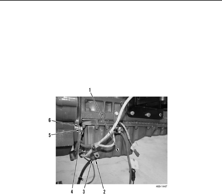
1. Remove two bolts (Figure 1, Item 4), washers (Figure 1, Item 5) and bracket (Figure 1, Item 6) from engine.
Position bracket aside.
2. Remove drain plug (Figure 1, Item 2) from engine oil pan (Figure 1, Item 1).
3. Remove O-ring (Figure 1, Item 3) from drain plug. Discard O-ring.
Figure 1. Engine Oil Drain Plug.
0090
4. Remove dipstick (Figure 2, Item 12) from oil level guide tube (Figure 2, Item 9).
5. Remove two O-rings (Figure 2, Item 13) from dipstick (Figure 2, Item 12). Discard O-rings.
6. Remove bolt (Figure 2, Item 8) from clip (Figure 2, Item 7).
7. Loosen nut (Figure 2, Item 10) and remove oil level guide tube (Figure 2, Item 9) from engine oil pan (Figure 2,
Item 1).
8. Remove and discard seal (Figure 2, Item 11) from end of oil level guide tube (Figure 2, Item 9).
WARN I N G
Engine oil pan may drop when bolts are removed. Support engine oil pan when removing
bolts. Failure to follow this warning may result in injury to personnel.
N OT E
Note position of breather hose clip to aid in installation.

