
TM 5-3805-293-23-3
0079
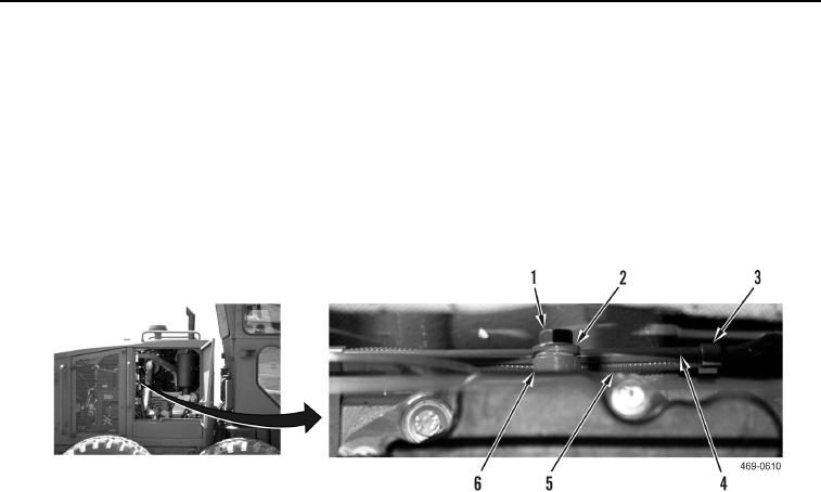
INSTALLATION CONTINUED
N OT E
Clip and bolt are located on back of cylinder head.
4. Install spacer (Figure 5, Item 6), clip (Figure 5, Item 2), inlet pressure tube (Figure 5, Item 4), and bolt
(Figure 5, Item 1) on cylinder head (Figure 5, Item 6).
5. Install inlet pressure tube (Figure 5, Item 4) on cylinder head (Figure 5, Item 6).
6. Install four clips (Figure 5, Item 5) on waste gate pigtail (Figure 5, Item 5) and inlet pressure tube (Figure 5,
Item 4).
Figure 5. Clamp and Clips.
0079