
TM 5-3805-293-23-3
0079
REMOVAL CONTINUED
C AU T I O N
Cap all lines, tubes, and openings to prevent contamination. Failure to follow this caution
may lead to failure of parts.
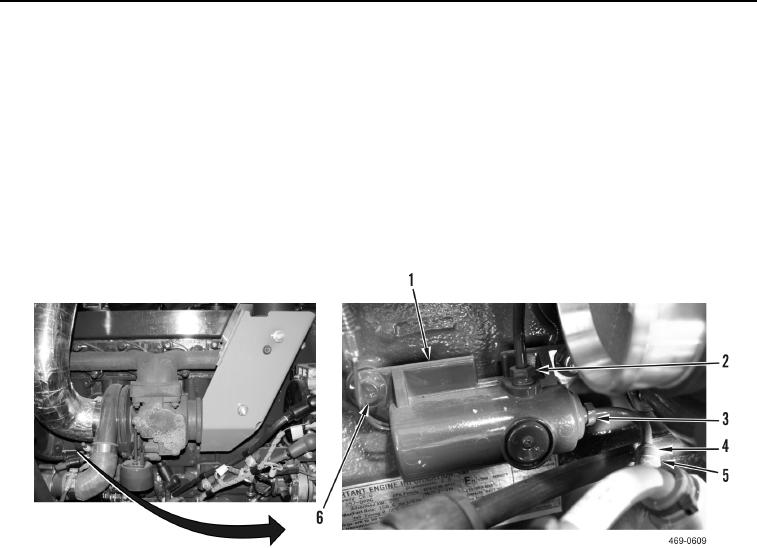
9. Remove clamp (Figure 4, Item 4) and inlet pressure hose (Figure 4, Item 5) from waste gate actuator (Figure 4,
Item 3).
10. Remove two inlet pressure tubes (Figure 4, Items 2 and 3) from waste gate solenoid (Figure 4, Item 1) and
machine.
11. Remove two bolts (Figure 4, Item 6) and waste gate solenoid (Figure 4, Item 1) from engine.
Figure 4. Waste Gate Solenoid.
0079
END OF TASK
CLEANING AND INSPECTION
00079
1. Clean and inspect all mechanical parts IAW Mechanical General Maintenance Instructions (WP 0346).
2. Clean and inspect all electrical parts IAW Electrical General Maintenance Instructions (WP 0347).
END OF TASK
INSTALLATION
00079
1. Install waste gate solenoid (Figure 4, Item 1) and two bolts (Figure 4, Item 6) on engine.
2. Install two inlet pressure tubes (Figure 4, Items 2 and 3) on waste gate solenoid (Figure 4, Item 1).
3. Install inlet pressure hose (Figure 4, Item 5) and clamp (Figure 4, Item 4) on waste gate actuator (Figure 4,
Item 3).