TM 5-3805-293-23-3
0061
INSTALLATION CONTINUED
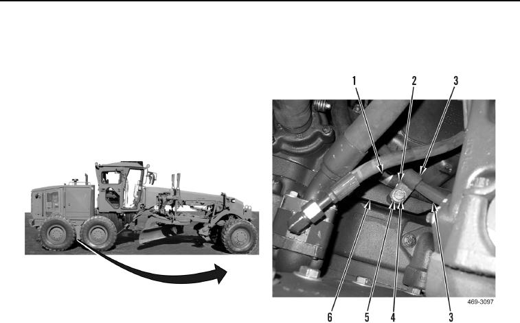
13. Install two clamps (Figure 10, Item 2), washer (Figure 10, Item 5), and bolt (Figure 10, Item 4), on two hoses
(Figure 10, Items 1 and 3) and bracket (Figure 10, Item 6).
Figure 10. Cooling Fan and Brake Piston Pump Hose Clamps.
0061
N OT E
Install all lines as marked and tagged during removal.
14. Install new O-ring (Figure 11, Item 15) and connect hose (Figure 11, Item 14) to fitting (Figure 11, Item 16).
15. Route hose (Figure 11, Item 11) on machine.
16. Install new O-ring (Figure 11, Item 19) and connect hose (Figure 11, Item 11) to pump (Figure 11, Item 13).
17. Install new O-ring (Figure 11, Item 2) and connect hose (Figure 11, Item 11) to manifold (Figure 11, Item 27).
18. Route tube (Figure 11, Item 5) on machine.
19. Install two new O-rings (Figure 11, Items 1 and 17) and connect tube (Figure 11, Item 5) to manifold (Figure 11,
Item 27) and fitting (Figure 11, Item 18).
20. Route tube (Figure 11, Item 4) on machine.
21. Install two new O-rings (Figure 11, Items 3 and 12) and connect tube (Figure 11, Item 4) to manifold (Figure 11,
Item 27) and pump (Figure 11, Item 13).
22. Install two clamps (Figure 11, Items 21 and 24), washer (Figure 11, Item 22), bolt (Figure 11, Item 23), washer
(Figure 11, Item 26), and nut (Figure 11, Item 25) on two hoses (Figure 11, Items 11 and 20).
23. Install four clamps (Figure 11, Item 6), two washers (Figure 11, Item 10), bolts (Figure 11, Item 9), washers
(Figure 11, Item 7), and nuts (Figure 11, Item 8) on two tubes (Figure 11, Items 4 and 5).

