
TM 5-3805-293-23-3
0061
INSTALLATION CONTINUED
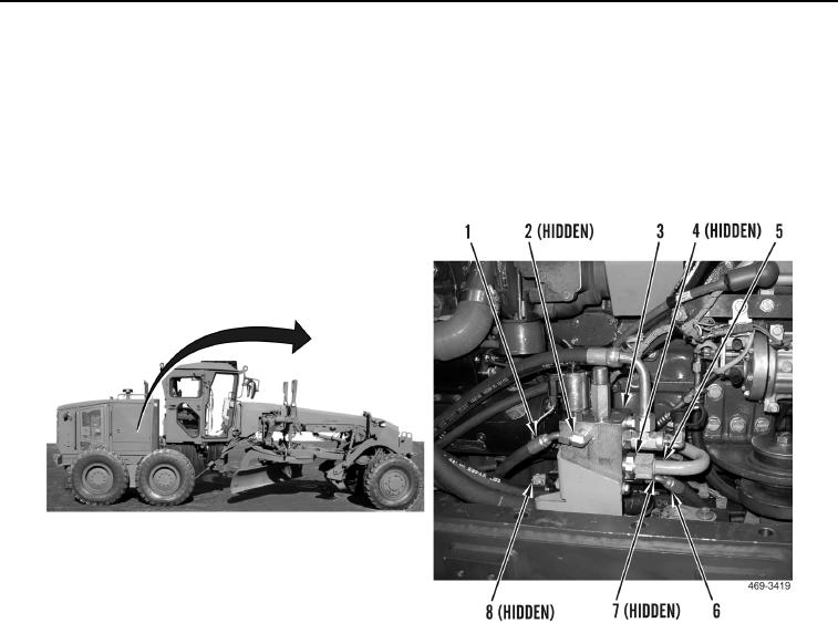
2. Route hose (Figure 7, Item 8) and tube (Figure 7, Item 5) on machine.
3. Install new O-ring (Figure 7, Item 4) and connect tube (Figure 7, Item 5) to control manifold (Figure 7, Item 3).
4. Install new O-ring (Figure 7, Item 7) and connect hose (Figure 7, Item 6) to control manifold (Figure 7, Item 3).
5. Route hose (Figure 7, Item 1) on machine.
6. Install new O-ring (Figure 7, Item 2) and connect hose (Figure 7, Item 1) to control manifold (Figure 7, Item 3).
Figure 7. Control Manifold Tube and Hose.
0061