TM 5-3805-293-23-3
0060
INSTALLATION CONTINUED
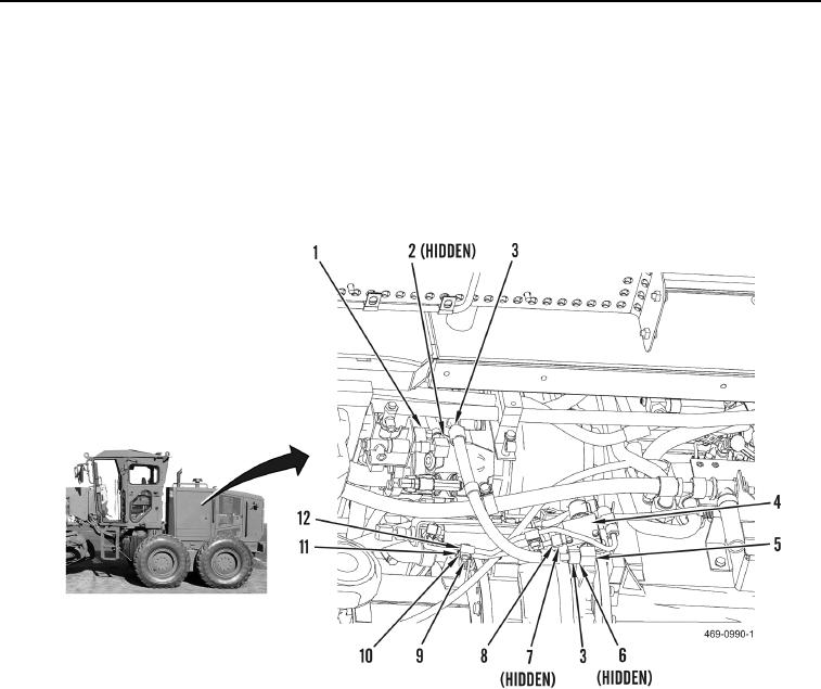
5. Install new O-ring (Figure 4, Item 2) and connect case drain hose (Figure 4, Item 3) to cooling fan and brake
piston pump (Figure 4, Item 1).
6. Install two new O-rings (Figure 4, Item 7) and connect tube (Figure 4, Item 8) to cooling fan and brake piston
pump solenoid valve (Figure 4, Item 4) and cooling fan and brake piston pump (Figure 4, Item 1).
7. Install two clamps (Figure 4, Item 12), nuts (Figure 4, Item 10), washers (Figure 4, Item 11), and bolts (Figure
4, Item 9) on tube (Figure 4, Item 8).
8. Install new O-ring (Figure 4, Item 6) and connect case drain hose (Figure 4, Item 3) on fitting (Figure 4, Item 5).
Figure 4. Cooling Fan and Brake Piston Pump Tube and Hose.
0060

