
TM 5-3805-293-23-3
0056
INSTALLATION CONTINUED
N OT E
Install all lines as marked and tagged during removal.
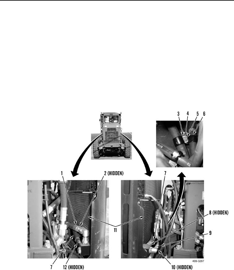
3. Route center hose (Figure 6, Item 7) on machine. Install new O-ring (Figure 6, Item 12) and connect center
hose to hydraulic oil cooler core (Figure 6, Item 11).
4. Install new O-ring (Figure 6, Item 2) and connect left-side hose (Figure 6, Item 1) to hydraulic oil cooler core
(Figure 6, Item 11) elbow.
5. Install new O-ring (Figure 6, Item 10) and connect right-side hose (Figure 6, Item 9) to hydraulic oil cooler core
(Figure 6, Item 11) elbow.
6. Install new O-ring (Figure 6, Item 8) and connect center hose (Figure 6, Item 7) to hydraulic oil cooler core
(Figure 6, Item 11).
7. Install two clamps (Figure 6, Item 4), washer (Figure 6, Item 5) and bolt (Figure 6, Item 6) on bracket (Figure 6,
Item 3).
Figure 6. Hydraulic Oil Cooler.
0056
END OF TASK