
TM 5-3805-293-23-3
0049
INSTALLATION CONTINUED
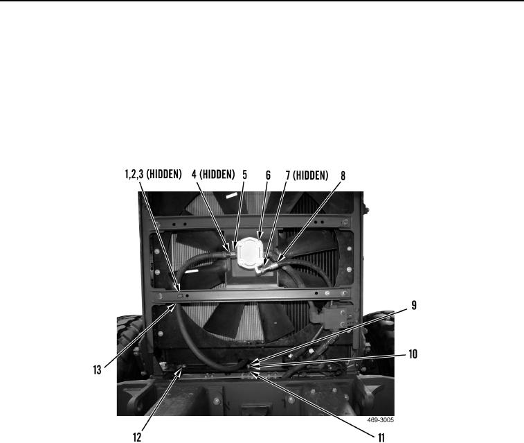
16. Install clamp (Figure 48, Item 3), washer (Figure 48, Item 2) and bolt (Figure 48, Item 1) on cooling fan gear
motor frame (Figure 48, Item 13).
17. Install clamp (Figure 48, Item 9), washer (Figure 48, Item 11) and bolt (Figure 48, Item 10) on cooling module
(Figure 48, Item 12).
18. Install new O-ring (Figure 48, Item 7) and connect drain hose (Figure 48, Item 8) to cooling fan motor
(Figure 48, Item 6). Discard O-ring.
19. Install new O-ring (Figure 48, Item 4) and connect hose (Figure 48, Item 5) to cooling fan motor (Figure 48,
Item 6). Discard O-ring.
Figure 48. Hydraulic Fan Motor Hoses.
0049