
TM 5-3805-293-23-3
0043
SPEED SENSOR TEST CONTINUED
00043
13. Disengage CREEP mode.
14. Place the transmission control switch in NEUTRAL position (TM 5-3805-293-10).
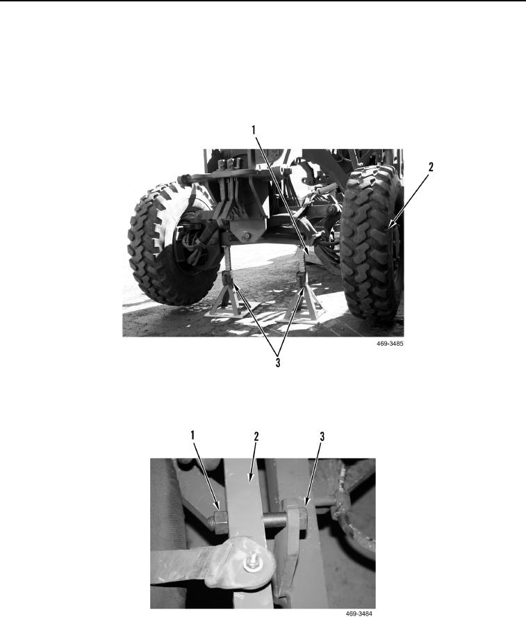
15. Lower blade (Figure 61, Item 1) until front axle is raised above vehicle support stands (Figure 61, Item 3).
16. Remove vehicle support stands (Figure 61, Item 3) and raise blade (Figure 61, Item 1) until front tires (Figure
61, Item 2) are on the ground.
Figure 61. Lift Front Wheels.
0043
17. Remove nut (Figure 62, Item 1) and wheel lean lock bolt (Figure 62, Item 3) from front axle (Figure 62, Item 2).
Figure 62. Wheel Lean Lock Bolt.
0043
18. Shut down the machine (TM 5-3805-293-10).
END OF TASK