
TM 5-3805-293-23-3
0043
SPEED SENSOR TEST CONTINUED
00043
11. Place transmission control switch in the FORWARD position (TM 5-3805-293-10).
a. Select maximum CREEP speed.
b. Ensure that the steering and the articulation are straight ahead.
c.
Both front wheels should spin in the forward direction.
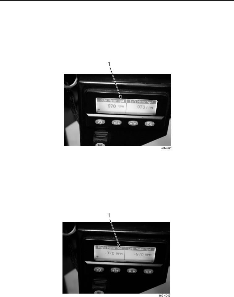
d. Motor speeds should be positive.
e. Motor speeds should be approximately 920 50 rpm (Figure 59, Item 1). Record speeds.
Figure 59. Positive RPM Display.
0043
12. Place transmission control switch in the REVERSE position (TM 5-3805-293-10).
a. Maintain maximum CREEP speed.
b. Ensure that the steering and the articulation are straight ahead.
c.
Both front wheels should spin in the reverse direction.
d. Motor speeds should be negative.
e. Motor speeds should be approximately -920 50 rpm (Figure 60, Item 1). Record speeds.
Figure 60. Negative RPM Display.
0043