
TM 5-3805-293-23-2
0034
CAN DATA LINK CIRCUIT TEST CONTINUED
49. Turn the battery disconnect switch and ignition switch to the ON position.
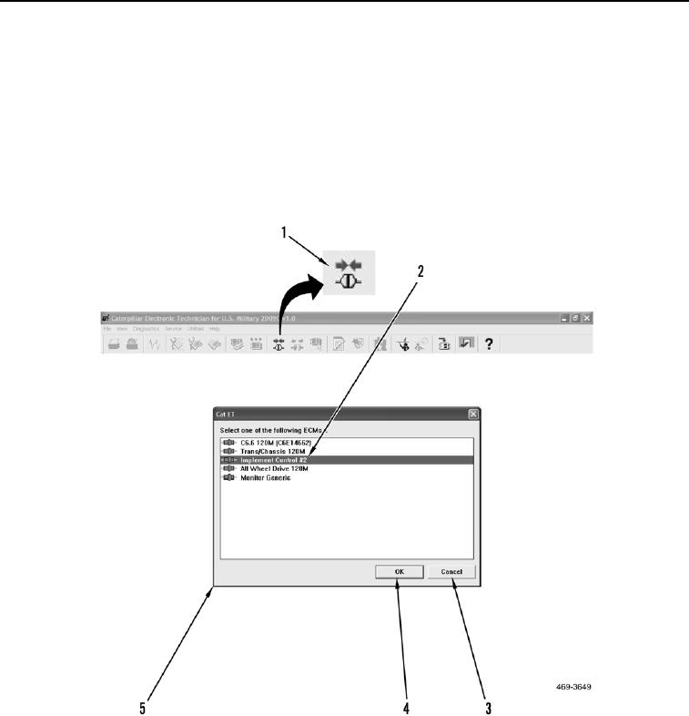
50. Select the Connect Icon (Figure 29, Item 1) at top of screen.
51. Observe ECMs from the popup window (Figure 29, Item 5). Implement Control #2 (Figure 29, Item 2) and four
other ECMs should be displayed.
a. If Implement Control #2 (Figure 29, Item 2) is not displayed, select the Cancel button (Figure 29, Item 3).
Replace Implement #2 ECM (WP 0268).
b. If Implement Control #2 (Figure 29, Item 2) is displayed, select the OK button (Figure 29, Item 4) proceed
to step 52.
Figure 29. ET Connect Icon and ECM Selection.
0034