
TM 5-3805-293-23-1
0003
BRAKING AND HYDRAULIC FAN SYSTEM CONTINUED
Hydraulic Fan
0003
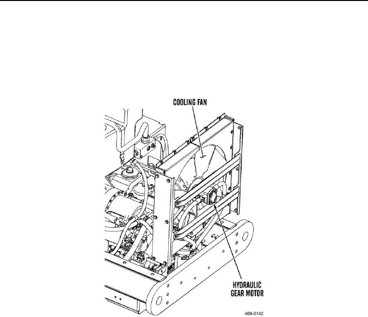
The hydraulic fan, or gear motor, is located in the cooling group. The fan is attached to the gear motor. The gear
motor converts hydraulic energy into mechanical energy in order to rotate the fan. The gear motor has an internal
makeup valve that allows the fan to stop gradually when the engine is shut down, preventing cavitation of the
motor. When the fan is spinning and there is no supply oil, the makeup valve redirects the oil inside the motor. Oil
will flow from the outlet side of the motor to the inlet side of the motor.
Figure 32. Cooling Fan and Motor.
0003