
TM 5-3805-293-10
0006
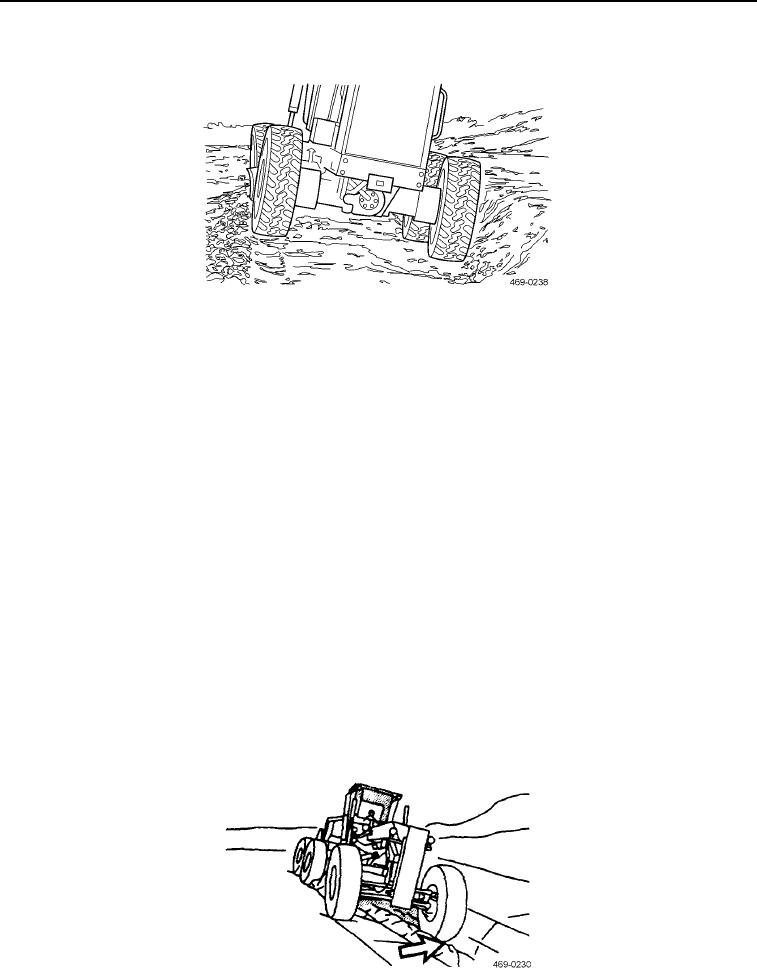
TRAVELING AND EARTH MOVING OPERATIONS CONTINUED
12. Repeat ditch cut as necessary.
Figure 47. Repeat Ditch Cut as Necessary.
0006
13. Back the grader along the outside edge of the windrow to the start point.
N OT E
Steps 14 through 26 pertain to cleaning the shoulder of the ditch.
This task is accomplished by placing the grader in the wide side reach position.
14. Position the grader so the right front tire is approximately 12-15 in. (30-38 cm) to the left of the ditch center line
and stop the grader.
15. Adjust the height of the blade to approximately 4-6 in. (100-150 mm) off the surface and then rotate the
moldboard to 0 degrees.
16. Center shift all the way to the right.
17. Readjust the height of the blade to approximately 2 in. (50 mm) off the surface.
18. Blade side shift all the way right.
C AU T I O N
Do not adjust the moldboard height, especially the heel (left lift) cylinder. The view is
obscured because the heel is under the main frame of the grader.
19. Circle the moldboard counterclockwise until the toe is approximately 12-15 in. (30-38 cm) from the outside
edge of the right front tire (approximately a 45 degree angle).
Figure 48. Setting Blade to Deliver Material.
0006
0006-25