POWER TRAIN
SPECIFICATIONS
TM 5-3805-263-14&P-2
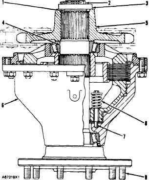
WHEEL SPINDLE
7 D 8 4 4 0
(7) Torque for bolts..
30 ± 5 lb. ft. (40 ± 7 N•m)
(8) 9J5498 Spring:
Length under test force
1 . 8 1 i n . ( 4 6 . 0 m m )
Test force
4 5 ± 2 . 2 5 l b . ( 2 0 0 ± 1 0 N )
Free length after test
2.71
in.
(68.8
mm)
Outside diameter
.825 in. (21.0 mm)
(9) Torque for studs
170 ± 22 lb. ft. (230 ± 30 N•m)
Assembly Procedure for the Wheel Spindle:
1. Assemble complete brake group with no shims (1) under
retainer (3).
2. Put flange end of wheel spindle (4) down.
3. Tighten bolts (2) to a torque of 35 lb. ft. (48 N•m) while
spindle housing (6) is turned.
4. Remove bolts (2) and retainer (3), but do not turn housing (6)
5. Measure distance from end of spindle (4) to end of sprocket
(5). Make a record of this measurement.
6. Install shams (1) of the thickness found in Step 5 minus .010 to
.015 in. (0.25 to 0.38 mm). If total shim thickness is more
than .040 in. (1.02 mm), use a 9D7047 Shim as part of the
shim thickness needed. If total shim thickness is more than
.060 in. (1.52 mm). use two 9D7047 Shims as part of the shim
thickness needed.
7. Install retainer (3) and tighten bolts
to a torque of
190 ± 10 lb. ft. (260 ± 14 N•m)
2-136