POWER TRAIN
TM 5-3805-263-14&P-2
ADJUSTMENT PROCEDURE FOR BACKLASH
OF RING GEAR AND PRELOAD OF
DIFFERENTIAL SUPPORT BEARINGS
THROUGH THE SIDE BORES IN THE
DIFFERENTIAL CASE
1. Disconnect the parking brake actuator by releasing it with
air pressure and removing the cotter pin and pin or use air
to keep the brake disengaged while adjustments are being
made.
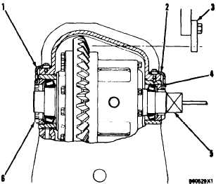
2. Remove locks (1) and (2) on bearing nuts (4) and (6). These
nuts are used to adjust the differential side bearing preloads.
3. Insert a drive axle shaft through both side gears of the dif-
ferential from the ring gear side (on nondifferentials. inser-
tion in one spline is enough). Turn the shaft with a pipe
wrench to rotate the differential as the bearings are being
adjusted.
4. Tighten nut (6) (on the side opposite the ring gear) as tight
as possible by hand while rotating the ring gear with the
axle shaft. The ring gear must be rotated for the bearings
to seat properly. While tightening nut (6) and rotating the
ring gear periodically, rock the ring gear against the bevel
gear so the backlash can be felt. An approximate backlash
of .010 in. (0.25 mm) should be established by loosening
or tightening nut (4) (ring gear side) while nut (6) is being
tightened.
5. When the approximate backlash of .010 in. (0.25 mm) has
been established, rotate the ring gear and tighten nut (4)
as tight as can be done with hands. Mark the position of
nuts (4) and (6) with a marking pen or something similar.
6. Tighten nut (4) an additional three notches.
7. An accurate backlash setting must now be made. Refer to
the Specifications section of the model being adjusted.
6. To measure the pinion to ring gear backlash, mount a dial
indicator with a magnetic base (5) to the end of the dif-
ferential housing assembly.
9. Fasten a block to one of the final drive mounting studs on
the main frame. Assemble dial indicator (5) so the indicator
plunger is against this block at a radius equal to the ring
gear diameter and will indicate the rotational movement of
the ring gear when it is rocked through its backlash with
the pinion gear.
10. Adjust nuts (4) and (6) equally to obtain the specified back-
lash. Check the marks made in Step 5 to assure a total
preload of three notches from band tight to the final locking
position has been maintained.
EXAMPLE: If nut (4) has to be loosened two notches, then nut (6)
should have been tightened two notches.
11. Install locks (1) and (2) that hold nuts (4) and (6) in position.
If the locks do not perfectly align in the notches, do not
advance the nuts more than a total of one half notch to align
the two locks.
2-134


