POWER TRAIN
TM 5-3805-263-14&P-2
TRANSMISSION
ASSEMBLE TRANSMISSION
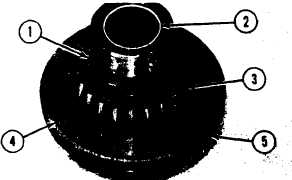
1. Install O-ring seal (5) on cage (4). Install
bearing (2) for the center shaft with tooling
(A).
2. Install bearing (3) and spacer (1) on cage
(4).
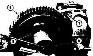
3. Put the cage in position in cover (7).
NOTE: Cover (7) is the cover from the transmis-
sion case that is over the studs for cage (4).
4. Install the nuts that hold the cover to the
cage. Put the cover in position in a vise.
5. Install input gear (6) and bearing (8) on the
cape. Put 4S9416 Anti-Seize Compound on
the face and threads of the nut for the
bearing. Install the lock and the nut that
hold the bearing. Tighten the nut with tool
(B) to a torque of 170 + 15 lb. ft. (23.5 ±
2.1 mkg). Bend the tab of the lock into the
nut.
6. Remove the cage from the cover. Remove
the cover from the vise. Put the cage and
the input gear in position on three blocks as
shown.
7. Install the bearings in gears (11) and (13).
Install the gears and the thrust washers in
carrier (9). install shafts (10) and (12) in
the carrier and the bearings for the gears.
Install the pins that hold the shafts to the
carrier. Put carrier (9) in position on the
input gear. Install the retaining ring that
holds it to the input gear.
CAUTION: The pins that hold the shafts to the
carriers must be installed even with the outer
surface of the carrier. If they are installed further,
they will prevent oil flow for lubrication to the
gears. This is the same on all pins for carriers in this
transmission.
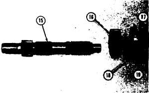
8. Install gear (16) on center shaft (15). Heat
bearing (18) in oil to a temperature of
275° F (135° C). lnstall the bearing on gear
2-98
DISASSEMBLY AND ASSEMBLY
(17) so the face of the bearing is even with
the face of the gear. Install ring (19) on the
bearing. Install the gear on the center shaft.