DISASSEMBLY AND ASSEMBLY
POWER TRAIN
TM 5-3805-263-14&P-2
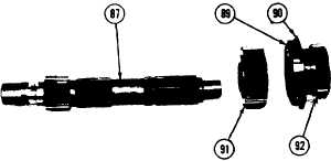
64. Remove gear (92) from the center shaft.
Remove bearing (89) from the gear. Re-
move retaining ring (90) from the bearing.
TRANSMISSION
65. Remove gear (91) from the center shaft.
66.
67.
68.
69.
70.
71.
72.
73.
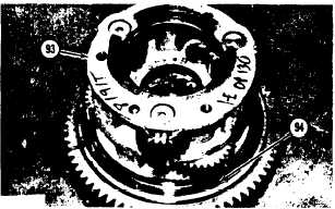
Remove retaining ring (94) with a screw-
driver.
Remove carrier (93) from the input gear for
the transmission.
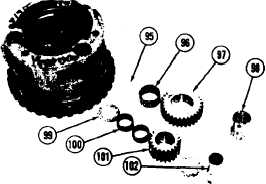
Move the pins that hold the shafts to the
carrier into the shafts with a punch and
hammer.
Remove shafts (98) and (102). Remove
gears (97) and (101).
Remove thrust washers (95) and (99) from
each side of the gears.
Remove two bearings (100) from gears
(101). Remove bearing (96) from gears
(97).
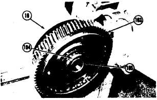
Rut cage (105) and the input gear in
position on cover (10). Install the nuts that
hold the cage to the cover. Put the cover in
a vise as shown.
Remove nut (104) with tooling (G). Re-
move the nut and the lock. Remove the
bearing and input gear (103) from the cage.
Remove the spacer and the other bearing
from the cage. Remove the cage from the
cover. Remove the bearing for the center
shaft from the cage. Remove the O-ring seal
from the cage.
2-96


