3304 VEHICULAR ENGINES
SPECIFICATIONS
TM 5-3805-263-14&P-2
FLYWHEEL
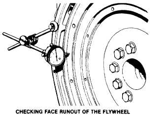
Face Runout (axial eccentricity) of the Flywheel:
1. Install the dial indicator as shown. Put a force on the flywheel
toward the rear.
2. Bet the dial indicator to read .000 in. (0.0 mm)
3. Turn the flywheel and read the indicator every 90°. Put a force on
the flywheel to the rear before each reading.
4. The difference between the lower and higher measurements
taken at all four points must not be more than .006 in. (0.15 mm),
which is the maximum permissible lace runout (axial eccentric-
ity) of the flywheel.
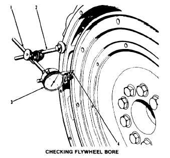
Bore Runout (radial eccentricity) of the Flywheel
1. Install the dial indicator (3) and make an adjustment of the uni-
versal attachment (4) so it makes contact as shown.
2. Set the dial indicator to read .000 in. (0.0 mm)
3. Turn the flywheel and read the indicator every 90°
4. The difference between the tower and higher measurements
taken at all four points must not be more than .006 in. (0.15 mm),
which is the maximum permissible bore runout (radial eccentric
ity) of the flywheel.
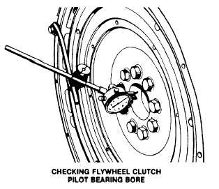
5. Runout (eccentricity) for the bore for the pilot bearing for the fly
wheel clutch, must not exceed .005 in. (0.13 mm)
1-248