ENGINE
DISASSEMBLY AND ASSEMBLY
9.
10.
11.
12.
13.
14.
CYLINDER HEAD
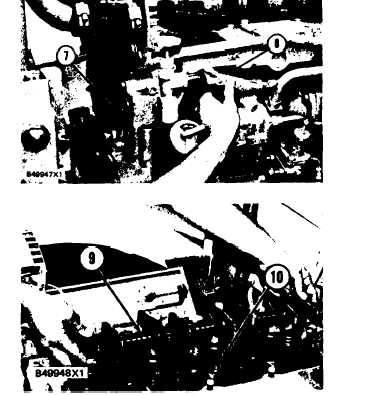
Install the gaskets and water pump elbow (7) to
the engine. Make sure to tighten the hose
clamps.
Connect hose (8) and tighten the clamp.
Install the elbow to the cylinder head and con-
nect the tube to the elbow.
Install push rods (10) and rocker shaft (9).
Install the bolts and washers.
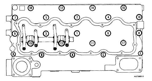
Tighten the bolts as follows:
a)
b)
c)
d)
e)
Tighten the bolts 1 through 18 in number
sequence to a torque of 155 N•m (115
lb.ft.).
Tighten bolts 1 through 18 again in number
sequence to a torque of 250 ± 17 N•m (185
± 13 lb.ft.).
Tighten bolts 1 through 18 again in number
sequence (hand tighten only) to a torque of
250 ± 17 N•m (185 ± 13 lb.ft.).
Tighten bolts A through E in letter se-
quence to a torque of 43 ± 7 N•m (32 ± 5
lb.ft.).
Tighten bolts A through E again in letter
sequence to a torque of 43 ± 7 N•m (32 ±
5 lb.ft.).
Make an adjustment until the intake valve
clearance is 0.38 mm (.015 in.) for the intake
and 0.64 mm (.025 in.) for the exhaust. See
VALVE CLEARANCE in TESTING AND
ADJUSTING.
TM 5-3805-263-14&P-2
end by:
a) install fan drive
b) install water regulator
c) install exhaust manifold
d) install fuel priming and primary filter
e) install air cleaner housing
f) install muffler
1-173


