ENGINE
DISASSEMBLY AND ASSEMBLY
TM 5-3805-263-14&P-2
FUEL INJECTION PUMP HOUSING AND GOVERNOR
16.
17.
18.
19.
20.
21.
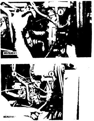
Install tooling (A) in the fuel injection pump
housing. Push on tool (A) and turn the fuel
injection pump camshaft. When tooling (A)
slides down into the groove (slot) in the fuel
injection pump camshaft, the fuel injection pump
is in the No. 1 piston top center position.
With tool (A) still in position remove the bolt
from fuel injection pump camshaft.
Install the washer and the bolt in the fuel injec-
tion pump camshaft. Make sure the washer is
installed with the large outside diameter toward
the bolt head. Tighten the bolt finger tight only.
Install tool (B) on the gear.
Use two torque wrenches to put a clockwise
force of 68 N•m (50 lb.ft.) on tool (B) to remove
the gear clearance (backlash) while the bolt is
tightened to a torque of 270 ± 25 N•m (199 ±
18 lb.ft.).
Check the timing as follows to make sure it is
correct:
a)
b)
c)
d)
Remove the timing pin from the pump cam-
shaft and the bolt from the flywheel.
Turn the crankshaft clockwise (as seen from
the front of the engine) approximately ½
turn. Install the timing pin again.
While the crankshaft is turned clockwise
(as seen from the front of the engine), push
on the timing pin (A) until it slides into the
groove (slot) in the pump camshaft.
Install the bolt in the flywheel.
NOTE: The timing is correct when the bolt is in-
stalled in the flywheel and the timing pin (A) is
installed in the groove (slot) in the pump camshaft.
22.
23.
24.
Remove the bolt from the flywheel.
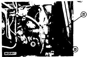
Install covers (20) and (22) on the fuel injec-
tion pump housing and the timing gear cover.
Tighten nuts (23) to a torque of 27 ± 7 N•m
(20 ± 5 lb.ft.).
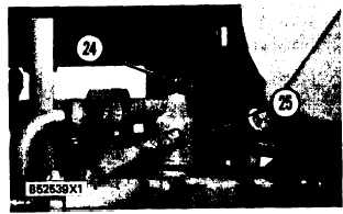
Put breather (25) in position on the valve cover.
Tighten the hose clamps. Tighten bolt (24) to a
torque of 14 ± 3 N•m (10 ± 2 lb.ft.).
end by:
a) install fuel lines
b) install fuel filter base and filter
1-137


