TM 5-3805-263-14&P-2
FUEL INJECTION PUMP HOUSING
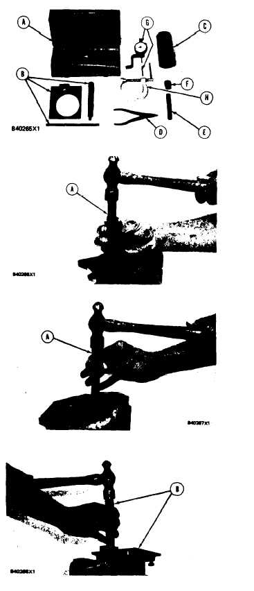
ASSEMBLE FUEL INJECTION
PUMP HOUSING
Tools Needed
A B C D E F G H
1P510 Driver Group
1
6V4818 Driver
1*
6V2016 Locator Plate
1*
6V4186 Timing Pin
1
FT1443
Sleeve
1
1P1859
Snap Ring Pliers
1
8S2244
Extractor
1
8S4613 Wrench
1
9S228
Rack Position Tool Group
1
3S3270
1 ¾” Contact Tip
1
C-Clamp
1
‘Part of 6V4095 Tool Group.
NOTE: Be sure all oil passages are clear and put
clean oil on all parts before assembly.
1. Use tool (A) to install the camshaft rear (gov-
ernor end) bearing. Install the bearing with the
junction (joint) toward the top of the fuel injec-
tion pump housing. Install the bearing so it is
1.00 ± 0.25 mm (.039 ± .010 in.) below the
surface of the housing.
2. Use tooling (A) to install the fuel rack rear
(governor end) bearing. Install the bearing so it
is 7.16 ± 0.13 mm (.282 ± .005 in.) below the
surface of the housing.
E N G I N E
DISASSEMBLY AND ASSEMBLY
3. Install the locator plate from tooling (B) on the
drive end of the fuel injection pump housing to
install the bearing for the fuel rack. Use clean
grease to hold the new fuel rack bearing on the
driver from tooling (C). Install the driver and
bearing in the plate with the groove in the
driver in alignment ‘with the pin in the plate and
use a hammer to push the bearing into position.
The bearing will be installed to the correct
depth when the shoulder of the driver is against
the plate.
1-142