DISASSEMBLY AND ASSEMBLY
TM 5-3805-263-14&P-3
MAIN FRAMES
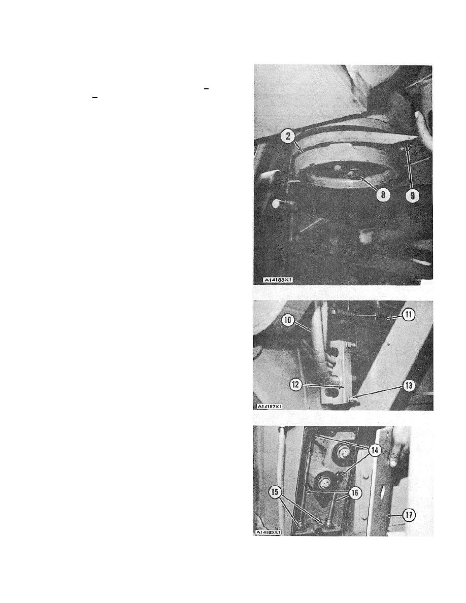
9. Remove the bolts that hold plate (2) to the
frame. Install two bolts (8) that hold the plate to
the pin. Tighten bolts (8) to a torque of 100 + 10
lb. ft. (135 + 14 N.m).
10. Measure the distance between the plate and the
frame with feeler gauge (9) at each bolt hole.
Remove bolts (8) and plate (2).
11. Install a thickness of shims same as the
minimum distance measured in Step 10 minus
.010 in. (0.25 mm) on plate (2). Put plate (2)
and shims in position on the bottom pin. Install
all the bolts that hold the plate to the pin and the
frame.
12. Remove the air supply from the parking brake
release valve.
13. Remove tooling (A) from under the front frame.
Remove the fork lift truck from the rear of the
rear frame.
14. Put all lines (10) in their correct locations in
clamps (12) on the front frame and the clamps
on the rear frame. Install nuts (13) on the four
clamps that hold the lines. Connect articulation
indicator linkage (11) to the rear frame. Install
the pin and the cotter pin.
15. Connect the electric wires, starter cable, and air
lines to their correct locations on the rear frame.
16. Connect the air lines and oil lines to their correct
locations on the front frame.
17. Connect transmission control cables (16) to their
correct locations in the housing. Install bolts(14)
and nuts (15) that hold the cables. Install cover
(17) and the bolts that hold the cover to the
housing.
18. Repeat Step 17 for the governor control cable
and the clutch control cable.
19. Fill the hydraulic tank with oil to the correct level.
end by:
a) install pump drive
b) install articulation cylinders
3-276


