DISASSEMBLY AND ASSEMBLY
TM 5-3805-263-14&P-3
MAIN FRAMES
SEPARATION OF MAIN FRAMES
Tools Needed
A
B
8S7630
Stand
2
8S7621
Tube
2
8S7625
Collar
2
8S7615
Pin
4
2
8S7650
Cylinder Assembly
2
8S7645
Hose Group
1
5P3100
Pump Group (or electric)
1
8S7640
Stand
2
8S7631
Tube
2
start by:
a) remove pump drive
b) remove articulation cylinders
1. Lower the blade to the ground. Release the air
pressure in the air tank by loosening the bleed
valves.
Do not disconnect any air lines from
the machine until the air pressure is
zero.
2. Drain the oil from the hydraulic tank. Put
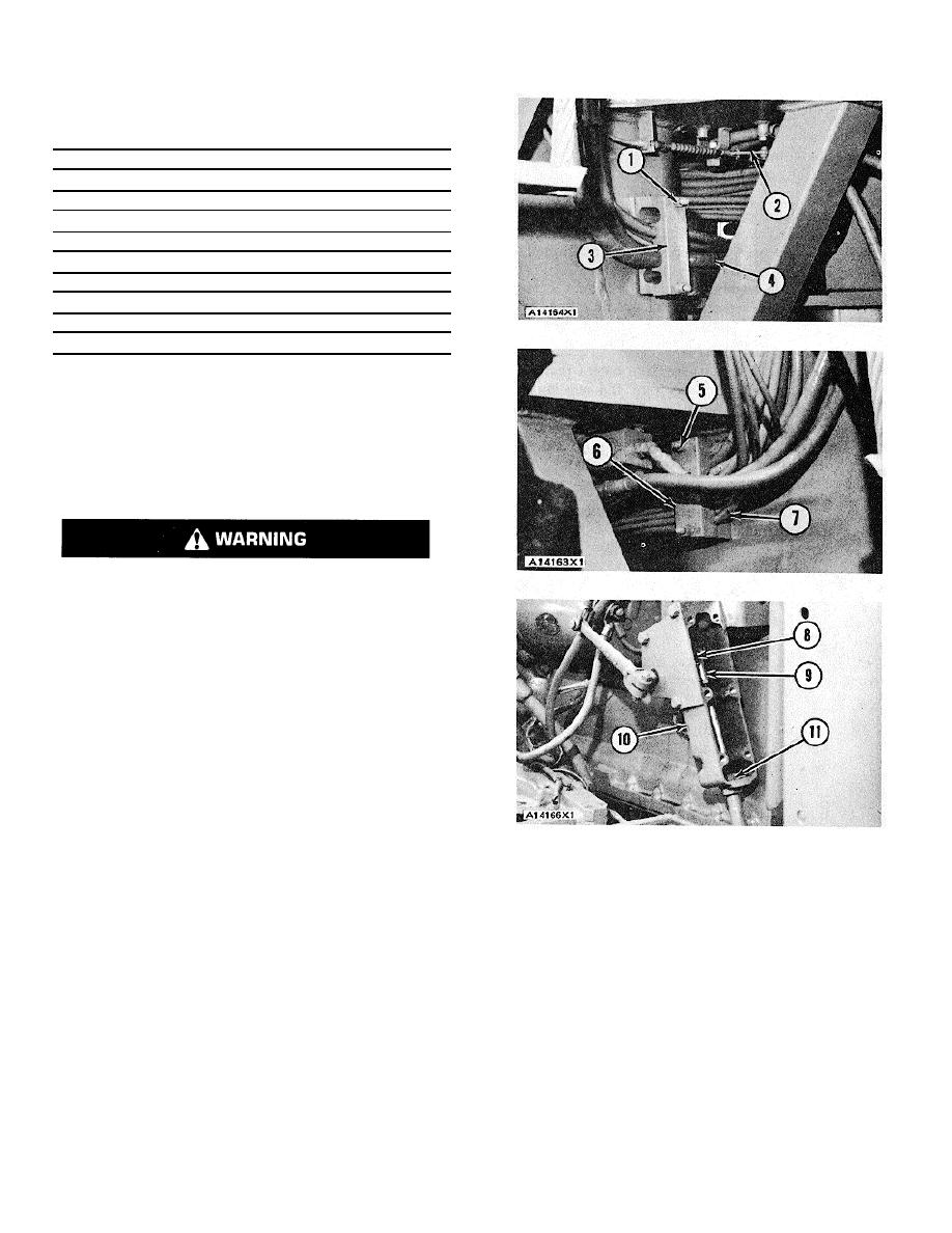
identification on the oil lines and air lines (4) on
the front frame on the left side. Remove nuts (1)
and clamp (3) that hold the lines. Remove the
nuts from the clamp on the rear frame on the
right side. Remove lines (4) from the two blocks.
Remove the cotter pin and the pin that hold
articulation linkage (2) to the rear frame.
Disconnect articulation linkage (2).
3. Put identification on lines (7) in clamp (6) on the
front frame on the right side. Remove nuts (5)
and clamp (6) from the lines. Remove the nuts
and the clamp from lines (7) on the rear frame
on the left side. Remove lines (7) from the
blocks. Disconnect the oil lines and the air lines
from the front frame. Disconnect the wires from
the rear frame.
4. Remove the bolts and the cover from governor
control housing (10). Remove bolt (8) that holds
rod end (9) to the lever. Remove rod end (8).
Remove nut (11) from the cable. Remove the
cable from the housing.
3-272


