VEHICLE SYSTEMS
TM 5-3805-263-14&P-3
MAIN FRAMES
CONNECTION OF MAIN FRAMES
Tools Needed
A
B
8S7630
Stand
2
8S7621
Tube
2
8S7615
Pin
4
2
8S7625
Collar
2
8S7650
Cylinder Assembly
2
8S7645
Hose Group
1
5P3100
Pump Group (or electric) 1
8S7640
Stand
2
8S7631
Tube
2
1. Put a fork lift truck in position under the rear of
the rear frame. Remove tooling (B) from under
the rear frame. Connect an air supply to the
parking brake release valve.
Release the
parking brake.
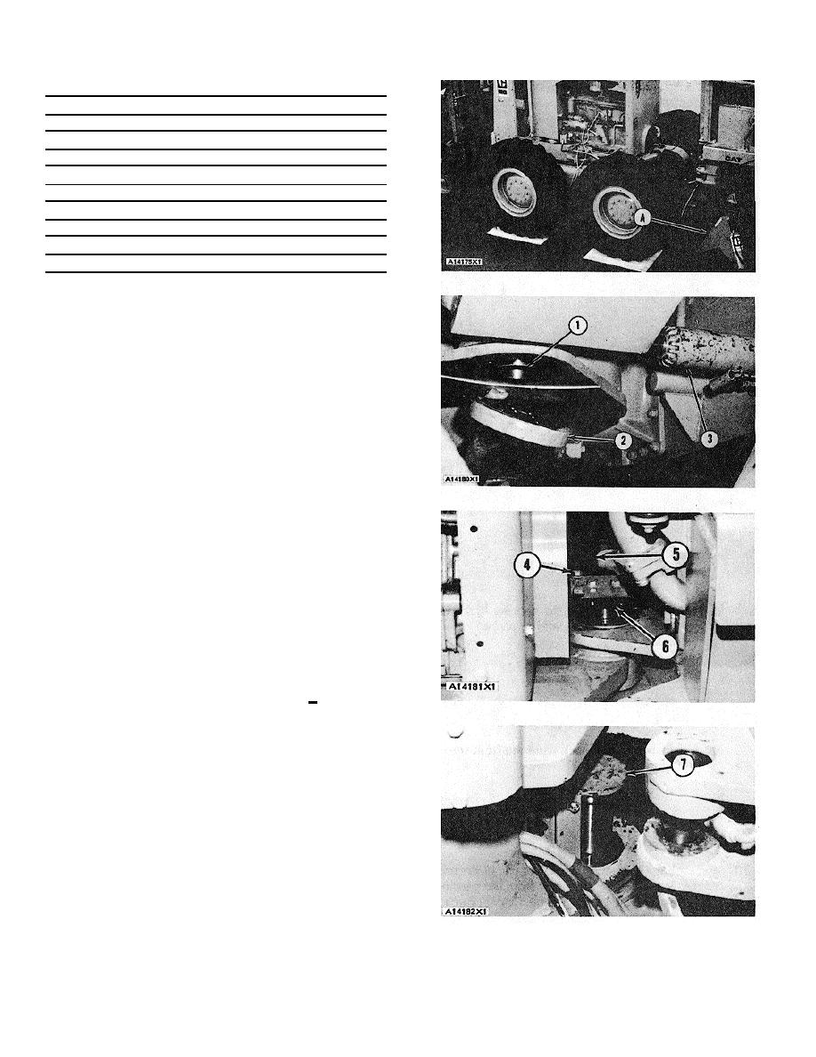
2. Move the rear frame into position on the front
frame with the fork lift truck.
3. Lift or lower the rear frame with the fork lift truck
to get the pin bore of the bottom pin in
alignment. Use a hydraulic jack (3) to put the
bore in alignment from side to side.
4. Put spacer (1) in position in the bottom pin bore
bearing and the rear frame. Install plate (2) on
the frame to hold the spacer.
NOTE
For easier pin installation lower the
temperature of the pins to -700F to -
900F (-570C to 680C).
5. Put pin (6) in position in the top pin bore. Make
sure the bolt holes in the cover for the pin are in
alignment with the bolt holes in the frame.
Install bolts (4).
NOTE
A bar (5) can be used to put the top
pin bore in alignment.
6. Tighten
bolts (4) evenly to a torque of 75 + 10
lb. ft.
(100 _ 14 N-m) with the
following procedure.
a) Tighten a bolt in the corner of the cover.
b) Tighten the bolt across from the bolt
tightened in Step a.
c) Tighten the next two bolts in the other
corners of the' cover.
7. Put bottom pin (7) in position in the bottom pin
bore. Install two long bolts through plate (2) and
into the bottom of the pin to help keep the holes
in the bottom of the pin in alignment with the
holes in the plate.
8. Install the pin. Remove the two long bolts.
3-275


