TM 5-3805-263-14&P-3
HYDRAULIC SYSTEM
AND STEERING
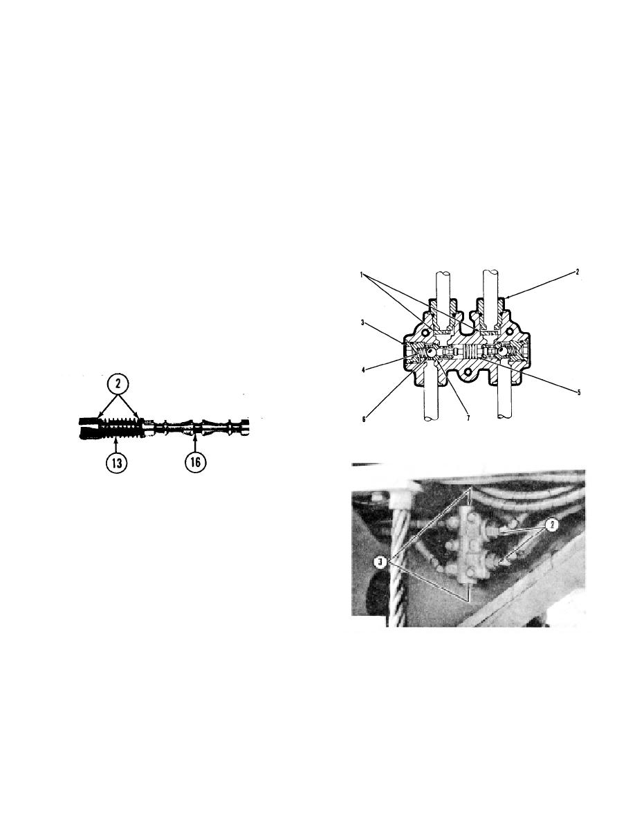
for the blade tip, and the ripper cylinder, have check
Valve Spool
valves with minimum resistance for the oil. There are
outlet chokes (1) in the check valves for the articulation
When either an adjustment for the location of valve
cylinders, the cylinder for center shift, and the lift cylinder
spool (1 6) is made, or when the valve spool is to be
for the blade on the right side of the machine. The check
removed, the housing and lever (9) must be removed
valve for the lift cylinder on the left side of the machine,
from the valve section.
has outlet chokes and also a relief valve in the passage
Cap lock (4) is removed when the adjustment for the
to the rod end of the lift cylinder.
location of the valve spool is made. The location for
A piston (5) that does not move easy in the check
valve spool (16) is correct when plug (3) is against the
valve is a cause for a hydraulic cylinder to move too
retainers and there is no end clearance for the valve
slow. Outlet chokes (1) that will not move away from the
spool.
fittings (2) is a cause for a hydraulic cylinder to move too
When plug (3) is not against the retainers, the unit of
slow. Balls (6) and seats (7) with rough surfaces is a
valve spool (16), spring (13) and retainers (2) have end
cause for cylinder rod drift.
clearance. When plug (3) is turned in too far, and it
moves the retainers at one end of spring ( 13) too near
the retainers at the other end of the spring, valve spool
(16) has end clearance between the retainers.
Install cap lock (4) when the adjustment for the
location of the valve spool is correct.
It may be necessary to turn the retainers at the top to
a position where the end of lever (9) can be installed in
the hole in the end of valve spool (1 6).
LOCK CHECK VALVE
1. Outlet chokes. 2. Fittings (two). 3. Plug (two). 4. Spring
(two). 5. Piston. 6. Ball (two). 7. Seat (two).
VALVE SPOOL
2. Retainers (two parts for each retainer). 13. Spring. 16. Valve
spool.
Valve spool (16), spring (13) and retainers (2) are
removed as a unit when either cover (21) is removed, or
cap lock (4) and plug (3) are removed from the valve
section.
Use new O-ring seals when the parts are installed in
the valve section.
LOCK CHECK VALVE
LOCK CHECK VALVE
There are three types of lock check valves in the
(For articulation cylinders)
hydraulic system. The piston (5), the seats (7), the
2. Fittings. 3. Plugs.
springs (4), and the plugs (3) in each of the three types
of check valves are the same. The leaning wheel
cylinder, the cylinder to side shift the blade, the cylinders
3-27


