TM 5-3805-263-14&P-3
HYDRAULIC SYSTEM
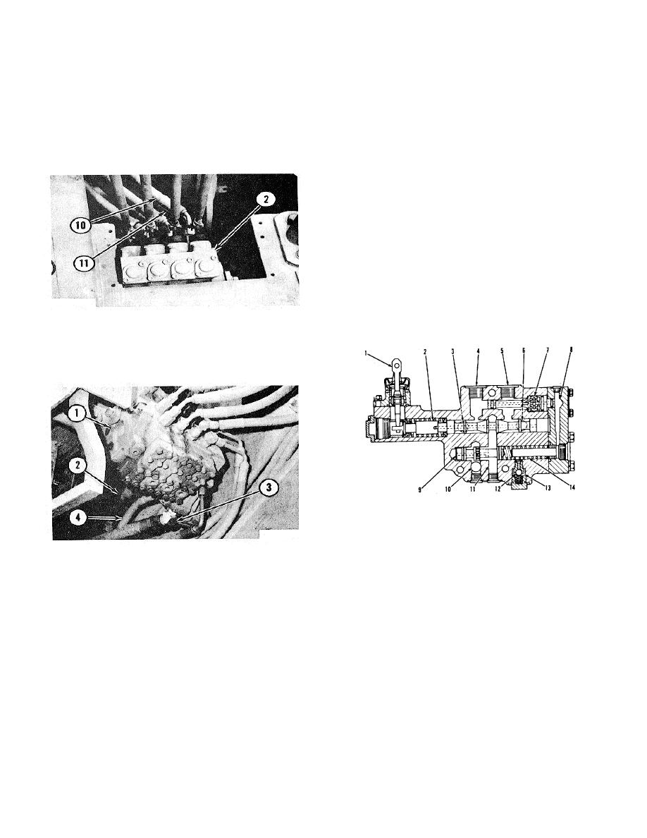
With the passages in the valves together, only one line
AND STEERING
for the pump oil (2) and one line for the return oil (3) is
(14) is the same as the pressure of the oil in line (10).
needed for all of the implement valves in a control valve.
When more force is needed to lower the blade, there is
an increase in the pressure of the pump oil to the head
Implement Valve
end of cylinder (4). When the pressure of the pump oil
The operation of each implement valve is the same.
goes to 1500 psi (103.5 kg/cm2), the oil in line (14)
There is a difference in each implement valve. The rate
moves the shuttle valve in the pump and the oil pressure
of oil flow (gpm, litre/min) from the outlets of each valve,
from the pump can go to approximately 3500 psi (246.1
to the implement, is not the same. The rate of oil flow
kg/cm2 ).
from each opening in an implement valve, for a hydraulic
cylinder, is not the same. There are implement valves
that have approximately the same rate of oil flow from
each opening. The size of the orifices from valve spool
(2), to openings (4) and (5), is one of the controls for the
rate of flow. The other control is the force of spring (14)
against valve (9). The spring force is not the same in
each implement valve.
Resolver valve (7) lets the oil with the higher pressure in
either the passage to opening (4), or the passage to
opening (5), go through the valve into passage (8). The
IMPLEMENT CONTROLS
higher pressure of the oil on the ball in valve (7) closes
2. Implement valve to raise or lower the blade (right
the valve passage with oil
side). 10. Line from implement valve to head of
cylinder. 11. Line from implement valve to rod end of
cylinder.
CONTROL VALVE FOR IMPLEMENTS
IMPLEMENT VALVE FOR A CYLINDER
1. Lever. 2. Valve spool. 3. Passage to tank. 4.
Opening for head end of a cylinder. 5. Opening for rod
end of a cylinder. 6. Passage to tank. 7. Resolver
CONTROL VALVE
valve. 8. Passage. 9. Valve for control of oil flow. 10.
1. Implement valves (four). 2. Line for pump oil. 3.
Passage from pump. 11. Passage. 12. Check valve.
Line for return oil. 4. Oil line to shuttle valve in variable
13. Passage for oil to shuttle valve in pump. 14. Spring.
displacement pump.
Each of the control valves for the implements, on each
side of the console for the control levers and steering
wheel, has 'four to five implement valves.
The
implement valves (1) are side by side and each valve is
approximately 1.5 in. (38.1 mm) thick. The passages for
the pump oil in each implement valve are together and
the passages for the
3-15


