TM 5-3805-263-14&P-3
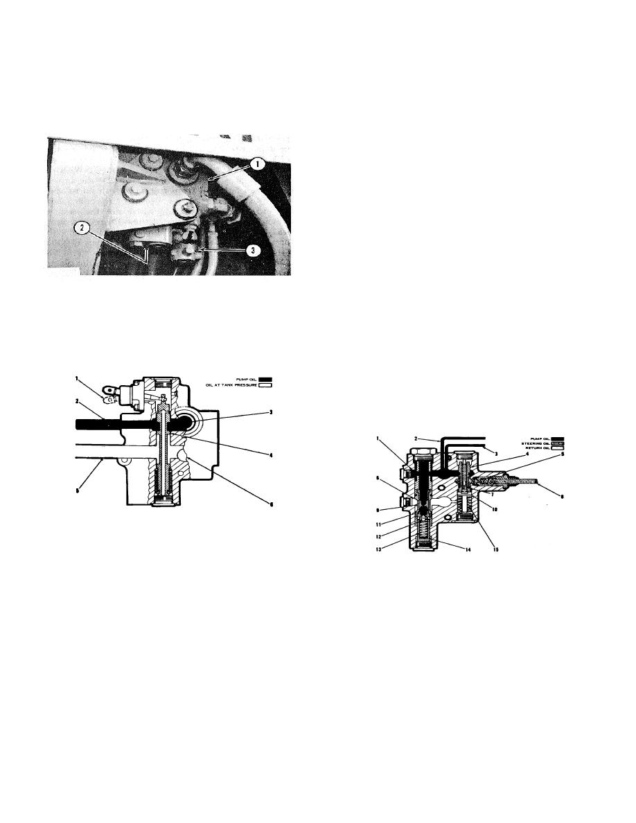
COMBINATION VALVE
SYSTEMS OPERATION
The oil from the variable displacement pump goes
through the combination valve when the engine is
The oil from the pump goes through line (2), around
running. The pump oil from the combination valve goes
valve spool (4) and through opening (3) to the other part
to the two control valves for the implements and to the
of the combination valve and to the hydraulic system.
metering valve for the steering.
The pistons, in the variable displacement pump, are at
their longest stroke as the engine is started. Because of
the closed hydraulic system and the pump at high output
gpm (litre/min), there is an added load on the starter
being used to start the engine. When the outside
temperature is low, the movement of the oil in the
hydraulic system is slow and the pump would put more
load on the starter when it is starting the engine. The
unloading valve can remove most of the hydraulic load
when the engine is being started. When the control lever
is held in UNLOAD position (1), valve spool (4) is moved
to let the pump oil through line (2) go along the groove
on valve spool (4) and go through line (5) to the tank.
VALVES IN THE COMBINATION VALVE
1. Unloading valve. 2. Pressure reduction valve. 3.
Relief Valve and Pressure Reduction Valve
Relief valve. A relief valve for the oil circuits to the control
The relief valve and the valve for the reduction of oil
valves for the implements (3), a valve that makes a
pressure for the steering system are in the same valve
reduction in the pressure of the oil from the-pump to the
housing. The relief valve is in the circuit from the pump.
steering system (2), and an unloading valve (1), are parts
The pressure reduction valve is in the same circuit as the
of the combination valve.
relief valve. The pump oil, through the valve to the
controls for the implements, can be as high as the
setting of the relief valve. The setting of the relief valve
is approximately 3900 psi (274.2 kg/cm2). The oil,
through pressure reduction valve to the steering system,
has a setting of a approximately 1825 psi (128.3 kg/cm2)
UNLOADING VALVE
(Part of combination valve)
1. Control lever UNLOAD position. 2. Line from pump.
3. Opening to other part of combination valve. 4. Valve
spool. 5. Line to tank. 6. Opening from other part of
8J7238 RELIEF VALVE AND VALVE FOR PRESSURE
combination valve.
REDUCTION
1. Passage for oil from pump. 2. Line to control for
implements. 3. Line to control for implements. 4.
Piston. S. Check valve. 6. Passage to tank. 7.
Passage in piston. 8. Line to steering system. 9. Dump
valve. 10. Washer and shims. 11. Spring for dump
valve. 12. Pilot valve. 13. Spring. 14. Shims. 15.
Springs (two, inner and outer).
3-10


