TM 5-3805-261-34
TRANSMISSION MAINTENANCE
14-10. Selector and Differential Control Valve. (Sheet 6
of 6)
ASSEMBLY
6.
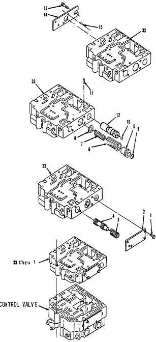
Install spool (18) and spring (17).
7.
Install new preformed packing (16) in cover (14).
8.
Install pin (15), cover (14) and three bolts (13) in
body (33,Figure 14-99). Tighten three bolts (13)
to 19 to 25 ft-lb. torque.
9.
Install stop (12) and dowel (11, Figure 14-93)
Dowel (11) must be installed 0.190 inch beneath
face of body (33).
10. Install ball (10) in body (33).
11. Install new preformed packing (9) on plug (5).
12. Install washer (8), springs (7 and 6) and plug (5).
13. Install spool (4) and spring (3, Figure 14-92).
14. Install cover (2) and four bolts (1). Tighten four
bolts (1) to 19 to 25 ft-lb. torque.
15. Install items 33 thru 1 as an assembly (Figure
14-
91) on control valves.
NOTE
Return 130CG Grader to
original equipment condition.
Figure 14-93.
End of Task
14-69
Figure 14-99.
Figure 14-92.
Figure 14-91.

