TM 5-3805-261-34
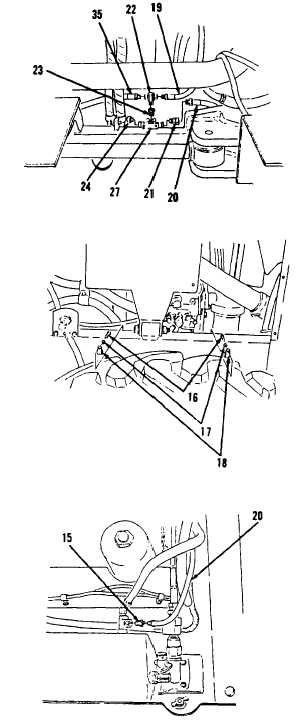
Figure 11-8.
Figure 11-7.
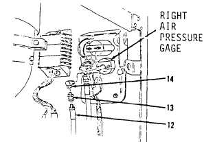
Figure 11-5.
Figure 11-6.
Go to Sheet 7
11-8
GAGES (NON-ELECTRICAL) MAINTENANCE. (cont.)
11-2. Air Pressure Gage to Air Tank Lines and Fittings. (Sheet 6 of 7)
INSTALLATION (cont.)
6.
Install plug (24), bushing (23)
and tee (22) on tee (27, Figure
11-8).
7.
Connect hose assembly (35) to tee
(22).
8.
Install connector (21) and hose
assembly (20) to tee (27).
9.
Connect air compressor hose
assembly (19) to tee (22).
10.
Install two clips (18), washers
(17) and bolts (16, Figure 11-7)
on left side of engine compart-
ment.
11.
Install connector (15, Figure
11-6) to air tank.
12.
Connect hose assembly (20) to
connector (15).
13.
Install elbow (14) and connector
(13, Figure 11-5) to right air
pressure gage at front, right
side of engine compartment.
14.
Install hose assembly (12) to