TM 5-3805-261-34
GAGES (NON-ELECTRICAL) MAINTENANCE.
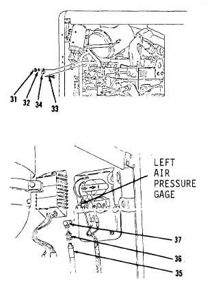
11-2. Air Pressure Gage to Air Tank Lines and Fittings. (Sheet 5 of 7)
REMOVAL
19.
Remove nut (31), washer (32),
bolt (33) and clip (34, Figure
11-11).
20.
Disconnect hose assembly (35)
from connector (36, Figure 11-12)
from front, right side of engine
compartment.
21.
Remove hose assembly (35) from
vehicle.
22.
Remove connector (36) and elbow
(37) from left air pressure gage.
CLEANING
Clean all parts. Refer to Chapter 2.
INSPECTION
Inspect all parts. Refer to Chapter
2.
INSTALLATION
1.
Install elbow (37) and connector
(36, Figure 11-12) on left air
pressure gage.
2.
Install hose assembly (35) on
connector (36).
3.
Install clip (34), bolt (33),
washer (32) and nut (31, Figure
11-11).
4.
Install two clips (30), washers
(29) and bolts (28, Figure
11-10).
5.
Install tee (27), two washers
(26) and bolts (25, Figure 11-9).
Go to Sheet 6
11-7
Figure 11-12.
Figure 11-11.