TM 5-3805-261-34
HYDRAULIC SYSTEM MAINTENANCE. (cont)
10-13.
Power Blade and Blade Tip Check and Relief Valve
ASSEMBLY
PRESSURE
PART NO.
THICKNESS
CHANGE
6J8696
0. 048 INCH
670 PSI
5J6153
0. 007 INCH
95 PSI
3K6116
0. 031 INCH
430 PSI
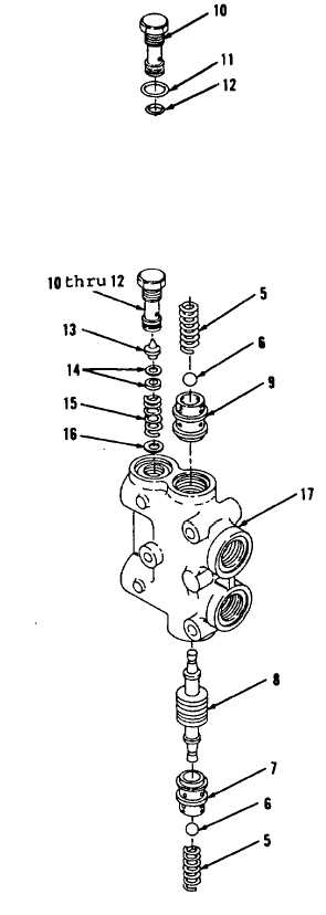
1.
Install washer (16), spring (15),
shim(s) (14, Figure 10-113) and
valve (13) in body (17). Use
washer (16) and shim(s) (14) as
required to obtain a relief valve
setting of 4000 psi at a flow
rate of 2. 5 gallons per minute.
Refer to chart.
2.
Install new preformed packings
(12 and 11) on plug (10, Figure
10-114).
3.
Lubricate outer diameter of new
preformed packings (12 and 11)
with clean lubricating oil.
4.
Install items 12 thru 10 as an
assembly.
5.
Using dry ice or freezer, reduce
temperature of seat (9) and
install using alignment punch and
hammer until seated against
counterbore in body (17).
6
Position piston (8) in seat (9)
in body (17).
7.
Using dry ice or freezer, reduce
temperature of seat (7) and
install using alignment punch and
hammer until seated against
counterbore in body (17). Check
for full movement of piston (8)
travel through seats (9 and 7).
Figure 10-114.
Figure 10-113.
Go to Sheet 5
10-78