TM 5-3805-261-23-2
BLADE LIFT BAR ASSEMBLY MAINTENANCE - CONTINUED
0340 00
ASSEMBLY - CONTINUED
3.
Use driver to install new seal (31). Lip of seal should be toward outside surface. Seal should contact ring (32).
4.
Use adapter puller, stud, nut, washer, and both hydraulic pullers to install four new bearings (35). Four bearings should
be at a depth of 0.390 to 0.422 in. (9.91 to 10.72 mm) from outside surfaces of blade lift bar (1).
5.
Install eight new seals (36). Lip of eight seals should be toward outside of bore. Eight seals should be even with outside
surface of blade lift bar (1).
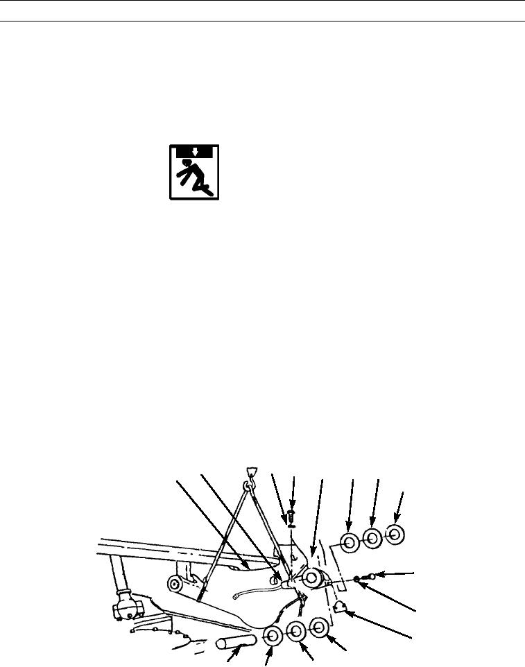
INSTALLATION
WARNING
Use extreme caution when handling heavy parts. Provide adequate support and use assistance during proce-
dure. Ensure that any lifting device used is in good condition and of suitable load capacity. Keep clear of
heavy parts supported only by lifting device. Failure to follow this warning may cause injury or death to per-
sonnel.
NOTE
Blade lift bar weighs 200 lb (91 kg).
1.
Attach sling to blade lift bar (1).
2.
Position blade lift bar (1) at blade lift arms (15).
3.
Install two washers (26, 27, and 28) between blade lift bar (1) and blade lift arms (15).
4.
Install pin (29). Groove in pin must align with opening in blade lift arm (15).
5.
Install lock (30), two washers (25), and bolts (24).
6.
Install washers (16, 17, and 18) between blade lift bar (1), and blade lift arms (15).
7.
Install pin (22). Groove in pin must align with opening in blade lift arm (15).
8.
Install lock (21), two washers (20), and bolts (19).
9.
Remove sling from blade lift bar (1).
10.
Install clip (12), new lockwasher (13), and bolt (14) in blade lift bar (1).
13
12
14
16
17
15
1
18
19
20
21
16
17
22
18
397-1675A
0340 00-5

