TM 5-3805-261-23-2
BLADE LIFT BAR ASSEMBLY MAINTENANCE - CONTINUED
0340 00
REMOVAL - CONTINUED
8.
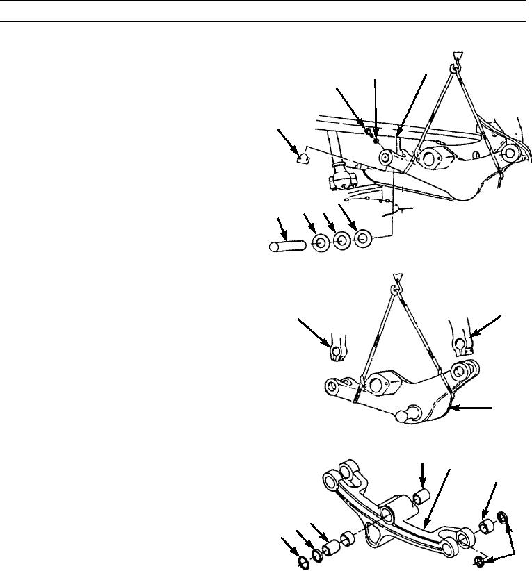
Remove two bolts (24), washers (25), and lock (30)
15
from right side blade lift arm (15).
25
24
9.
Remove pin (29) and washers (26, 27, and 28).
30
26
28 27
29
397-1676
10.
Remove blade lift bar (1) from blade lift arms (15) and
place in work area.
11.
Remove sling.
15
15
1
397-1677
DISASSEMBLY
1.
Use adapter puller to remove eight seals (36) and four
34
1
bearings (35). Discard seals and bearings.
35
2.
Use adapter puller to remove seal (31), ring (32), bear-
ing (33), and bearing (34) from blade lift bar (1). Dis-
card seal and bearings.
33
32
31
36
397-1678
CLEANING AND INSPECTION
Clean and inspect all parts in accordance with WP 0020 00.
ASSEMBLY
1.
Install ring (32) in blade lift bar (1).
2.
Use adapter puller, stud, nut, washer, and both hydraulic pullers to install new bearing (34), and new bearing (33). Bear-
ings must seat on ring (32)
0340 00-4

