
TM 5-3805-261-23-2
ELECTRONIC MONITORING SYSTEM (EMS) MAIN
WIRING HARNESS REPLACEMENT - CONTINUED
0291 00
REMOVAL
NOTE
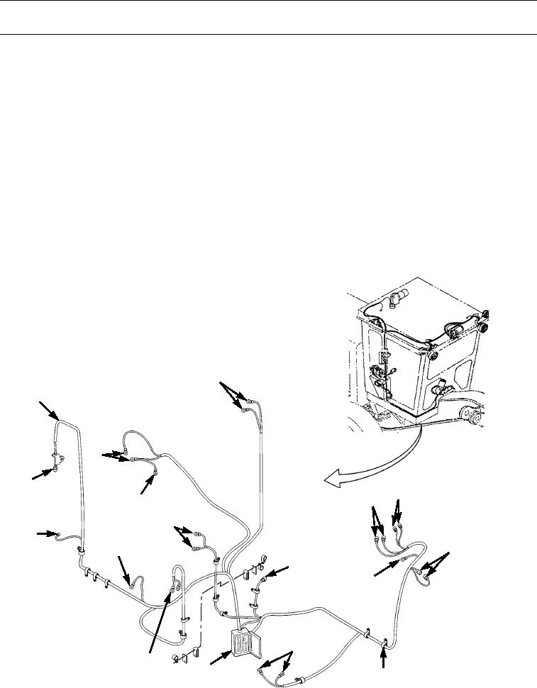
Tag and note routing of wiring harness before disconnecting to aid in installation.
1.
Disconnect EMS wiring harness (1) from test switch (8) (WP 0070 00), lamp (9) (WP 0071 00), EMS panel (7) (WP
0069 00), supplemental steering (10) (WP 0086 00), air pressure switches (12) (WP 0112 00), fuse box (13) (WP 0096
00), warning horn (6) (WP 0119 00), coolant temperature switch (5) (WP 0114 00), engine oil pressure switch (2) (WP
0113 00), hourmeter switch (3) (WP 0113 00), hydraulic oil temperature switch (4) (WP 0116 00), fuel pressure switch
(14) (WP 0115 00), starting motor (15) (WP 0067 00), alternator (16) (WP 0066 00), and jumper wire (17).
2.
Remove clips/clamps (11) and tie straps. Discard tie straps.
NOTE
For Type II machines, wiring harness is divided between sections of machine.
3.
Remove EMS wiring harness (1) from machine.
5
1
2
17
9
8
3
4
16
10
15
6
7
12
14
13
11
397-4093
0291 00-2