
TM 5-3805-261-23-2
GOVERNOR CONTROLS MAINTENANCE - CONTINUED
0282 00
REMOVAL - CONTINUED
NOTE
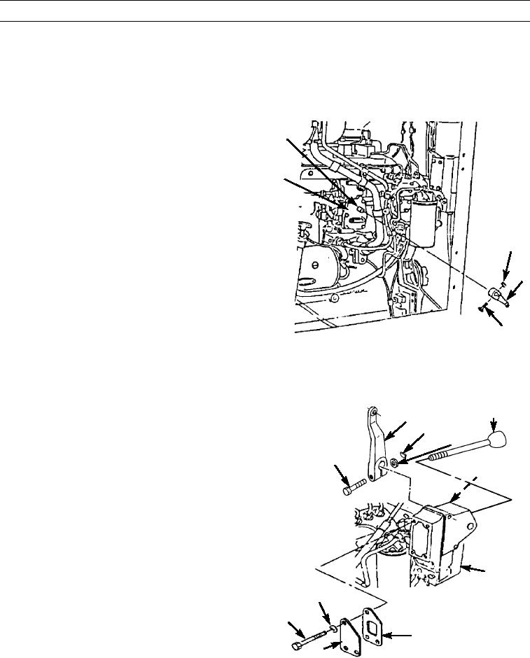
Matchmark lever and fuel injection pump governor shaft to aid in aligning lever on fuel injection pump gov-
ernor shaft during installation to fuel injection pump governor (17).
12.
Remove nut (14) and bolt (16).
13.
Remove lever (15) from fuel injection pump governor
13
shaft. (13).
17
14
15
16
397-1420
14.
For Type II machines, unscrew rear governor control
REAR GOVERNOR
lever.
CONTROL LEVER
19
15.
Remove nut (21) and bolt (18) from inner-right side of
20
dash panel in engine compartment.
21
16.
Remove lever (19) from shaft (22) on inside of hous-
18
ing (23).
22 (HIDDEN)
17.
Remove key (20) from shaft (22).
18.
Remove four bolts (26), washers (27), cover (25), and
gasket (24). Discard gasket.
19.
Support housing (23).
23
27
26
24
25
397-1421
0282 00-3