
TM 5-3805-261-23-2
FUEL INJECTION PUMP REPLACEMENT - CONTINUED
0279 00
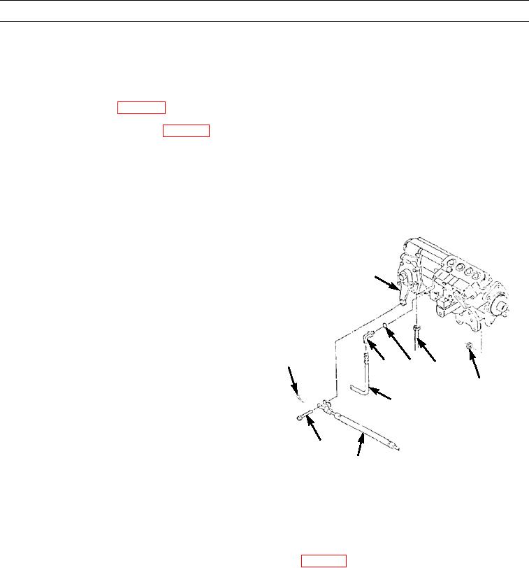
INSTALLATION - CONTINUED
5.
Remove hoist.
6.
Install three nuts (1).
7.
Install manifold shield (WP 0277 00).
8.
Install governor control lever (9) (WP 0282 00).
CAUTION
After the fuel injection pump and governor are installed, move governor control lever back and forth. Pre-
formed packing can hold rack and prevent free movement. If rack does not move freely, remove fuel injec-
tion pump and governor and reset preformed packing.
9.
Connect hose assembly (5).
10.
Install hose assembly (2), new preformed packing (3),
and elbow (4).
9
11.
Position linkage assembly (6) on governor control
lever (9).
12.
Install pin (7) and new cotter pin (8).
8
3
4
2
1
5
7
397-1344
6
CAUTION
Do not attempt to start engine until fuel injection pump and governor have been adjusted.
13.
Install fuel transfer pump (Models 130G, 130GSCE, 130GNSCE) (WP 0281 00).
14.
Install tachometer drive (Models 130G, 130GSCE, 130GNSCE) (WP 0034 00).
15.
Install secondary fuel filter and mounting (WP 0047 00 or WP 0048 00).
16.
Install fuel injection lines (WP 0035 00).
17.
Install turbocharger oil lines (WP 0033 00).
18.
Install engine hood (WP 0181 00).
0279 00-5