TM 5-3805-261-23-2
ROCKER ARM ASSEMBLY MAINTENANCE - CONTINUED
0273 00
ADJUSTMENT - CONTINUED
NOTE
Number one cylinder must be at compression stroke for proper valve adjustment.
6.
Check number one cylinder for compression stroke. Intake and exhaust valves must be closed. This can be checked by
visually inspecting the valves and by movement in both rocker arms. If exhaust valve is open, remove 3/8-16NC bolt
and turn engine 360 degrees.
7.
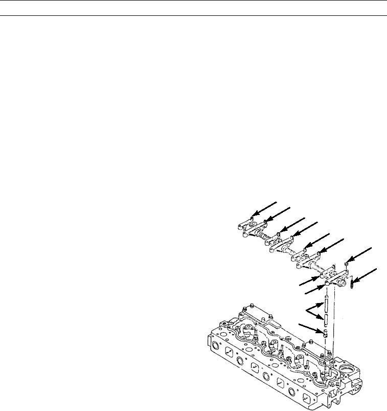
Adjust intake valves for cylinders 1 and 2. Turn adjusting screws (13) in arms (18 and 29) until a clearance of 0.012 to
0.018 in. (0.30 to 0.46 mm) is obtained. Secure screws (13) with nuts (8).
8.
Adjust exhaust valves for cylinders 1 and 3. Turn adjusting screws (13) in arms (14 and 34) until a clearance of 0.022 to
0.028 in. (0.56 to 0.71 mm) is obtained between arms (14 and 34) and push rods (6). Secure screws (13) with nuts (8).
NOTE
Remove 3/8-16NC bolt from flywheel before turning engine.
9.
Turn engine counterclockwise 360 degrees. Verify
56
51
that number 4 cylinder is at TC position.
37
10.
Install 3/8-16NC bolt in flywheel.
34
29
11.
Adjust intake valves for cylinders 3 and 4 by turning
25
screws in arms (37 and 56). Repeat adjustment proce-
8
dures in step 7.
12.
Adjust exhaust valves for cylinders 2 and 4 by turning
13
screws in arms (25 and 51). Repeat adjustment proce-
dures in step 8.
18
13.
Tighten eight nuts (8). Hold adjusting screws and
14
tighten eight nuts to 22 lb-ft (30 Nm).
6
5
397-1322
14.
Remove engine turning gear.
15.
Remove 3/8-16NC bolt from flywheel housing.
16.
Install valve cover (WP 0031 00).
END OF WORK PACKAGE
0273 00-9/(-10 Blank)

