TM 5-3805-261-23-2
VALVES MAINTENANCE - CONTINUED
0274 00
REPAIR
1.
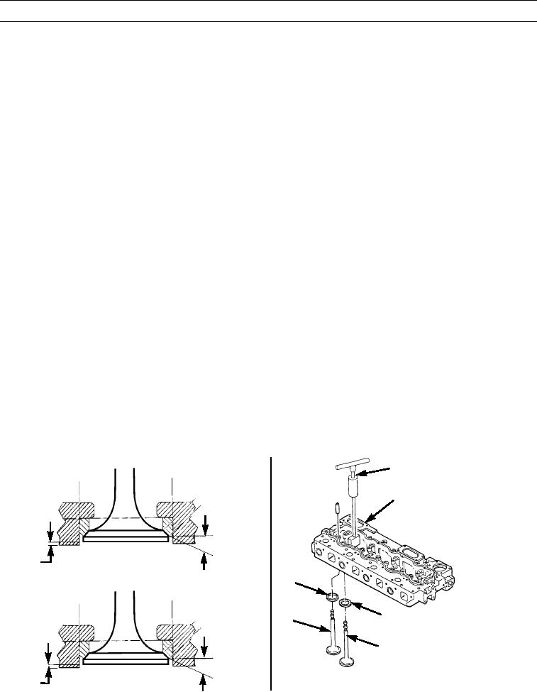
Grind four exhaust valve seats (7) and intake washers (8) to an angle of 30 degrees.
NOTE
To reduce maximum seat angle, grind seat face to 15 degrees.
2.
Grind seat face to 15 degrees, if necessary.
NOTE
Valves must be matched with the exhaust valve seat or intake washer with which they are measured. Mark
valve and matching valve seat or washer to identify matching sets.
3.
Measure valve recess for four exhaust valve seats (7). Minimum dimension between combustion surface and exhaust
valve (9) face is 0.026 in. (0.66 mm).
4.
Measure valve recess for four intake washers (8). Minimum dimension between combustion surface and intake valve (5)
face is 0.006 in. (0.15 mm).
5.
Match and mark four exhaust valves (9) and intake valves (5) with their respective exhaust valve seats or intake wash-
ers.
NOTE
Angle of exhaust and intake valves must be 29-1/4 degrees.
6.
Grind four exhaust valves (9) and four intake valves (5).
7.
Apply prussian blue to face of four exhaust valves (9) and intake valves (5) and install into matchmarked valve seat (7)
or intake washer (8) respectively.
NOTE
In the following step, if blue is transferred to center of valve face, contact is correct. If blue is transferred to
top of valve face, lower valve seat or washer by grinding. If blue is transferred to bottom edge of valve face,
raise valve seat or washer by grinding.
8.
Turn valve stem allowing valve face to lightly contact face of valve seat or washer. Remove valve. Observe blue trans-
fer, grind as necessary.
VALVE SEAT EXTRACTOR
2
15o
EXHAUST
0.26 IN.
(0.66 MM)
8
5
7
9
15o
0.006 IN.
INTAKE
397-2506
(0.15 MM)
397-1325A
0274 00-4

