TM 5-3805-261-23-1
CIRCLE DRIVE AND LEANING WHEEL CHECK VALVE MAINTENANCE - CONTINUED
0239 00
INSTALLATION
NOTE
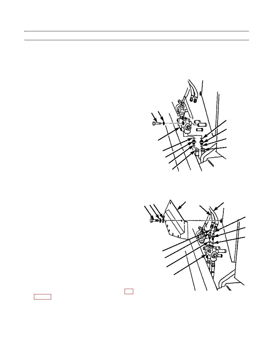
Perform steps 1 through 12 to install leaning wheel check valve.
1.
Install leaning wheel check valve (9) to machine with
washer (37) and bolt (36).
2.
Install new preformed packing (45) and connector
(44).
3.
Install new preformed packing (38) and connector
36 37
(39).
38
4.
Install new preformed packings (43 and 40) and con-
nect hose assemblies (42 and 41) to connectors (44
39
and 39).
40
9
41
45
44
43
42
397-678
5.
Install new preformed packing (33) and elbow (34).
27
29
24 25 26
28
6.
Install new preformed packing (32) and elbow (31).
7.
Install new preformed packings (30 and 35) and con-
30
nect two hose assemblies (29 and 28) to elbows (31
and 34).
31
NOTE
32
If circle drive check valve was removed,
install per steps 13 through 24 before start-
35
ing engine.
34
8.
Start engine (TM 5-3805-261-10).
9.
Operate control levers and cycle system through five
33
or more full-travel movements to bleed air from sys-
9
tem.
10.
Stop engine and check for leaks.
11.
Check hydraulic oil level and fill as necessary (WP
397-677
12.
Install frame cover (27) to machine with eight washers
(26 and 25) and bolts (24).
0239 00-8


