TM 5-3805-261-23-1
SUPPLEMENTAL STEERING GOVERNOR SWITCH WIRING HARNESS REPLACEMENT
THIS WORK PACKAGE COVERS
Removal, Cleaning and Inspection, Installation
INITIAL SETUP
Equipment Conditions
Maintenance Level
Unit
Machine parked on level ground (TM 5-3805-261-
10)
Tools and Special Tools
Parking/emergency brake applied (TM 5-3805-261-
Tool kit, general mechanic's (Item 89, WP 0348 00)
10)
Materials/Parts
Implements lowered to ground (TM 5-3805-261-
Rag, wiping (Item 35, WP 0349 00)
10)
Strap, tie (Item 43, WP 0349 00)
Engine off (TM 5-3805-261-10)
Tag, marker (Item 44, WP 0349 00)
Battery cables disconnected (WP 0125 00)
References
Right side engine doors opened (TM 5-3805-261-
10)
REMOVAL
1.
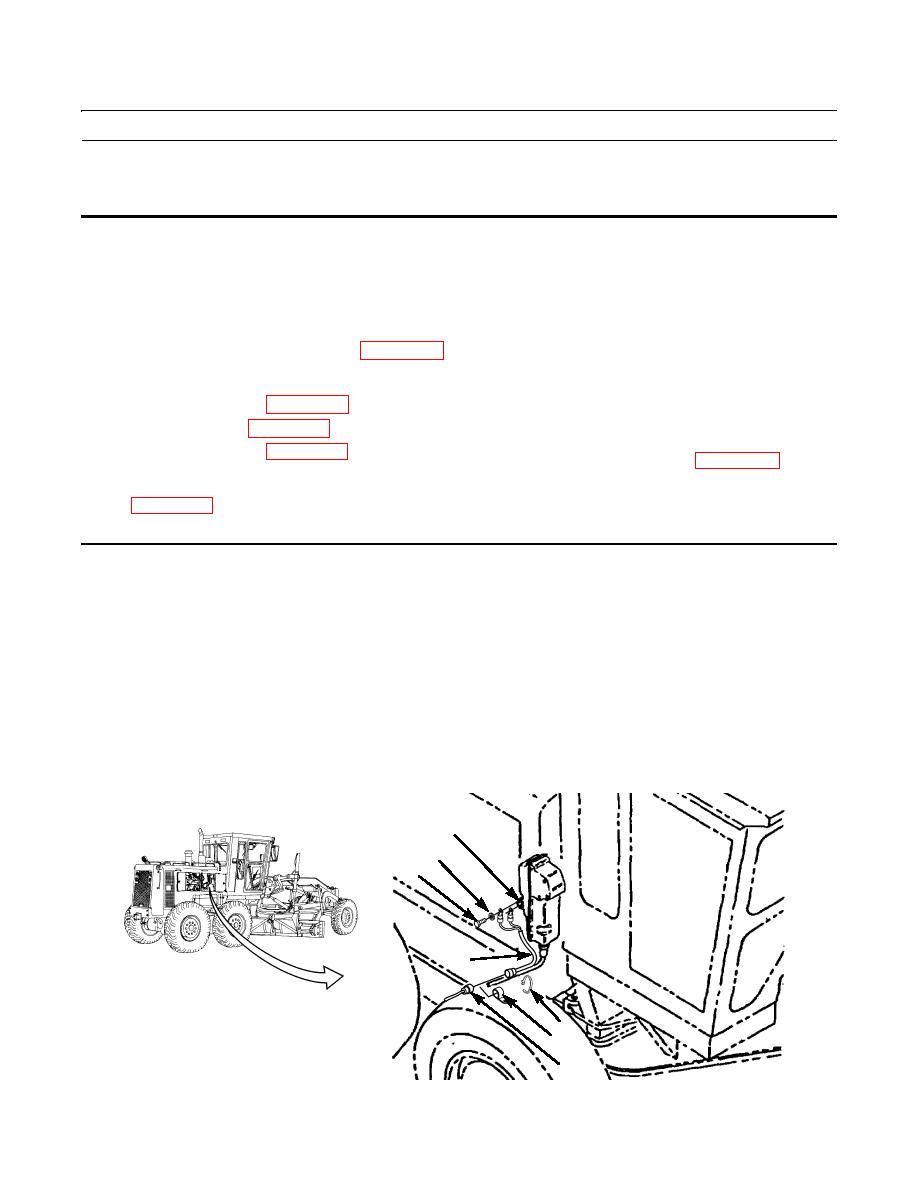
Remove and discard tie strap (1).
NOTE
Tag wiring harnesses before disconnecting to aid in installation.
2.
Remove two screws (5), washers (6), and disconnect governor switch wiring harness (4) from supplemental steering
governor switch (7).
3.
Remove governor switch wiring harness (4) from main wiring harness (3).
4.
Remove clip (2).
7
6
5
4
1
2
3
397-409


