TM 5-3805-261-20
BODY, CAB, HOOD AND HULL MAINTENANCE. (cont)
13-15.
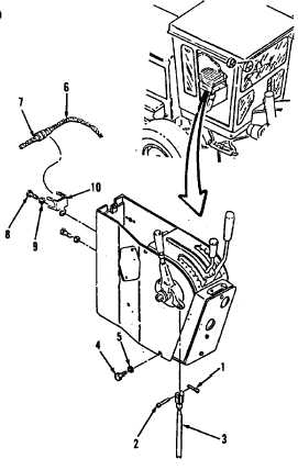
Operator’s Panel Console. (Sheet 2 of 6)
REMOVAL
1.
Remove seat. Refer to paragraph 13-21,
steps 1 and 2.
2.
Remove cotter pin (1) and clevis pin (2)
from right side of operator’s panel console,
inside of cab. Discard cotter pin (1). Lay
linkage rod (3, Figure 13-52) to one side.
3.
Remove four bolts (4) and washers (5).
4.
Separate
harness
assembly
(6)
from
bracket (10) in rear of operator’s panel
console.
NOTE
All
wire,
cable
and
harness
assemblies must be tagged before
disconnecting to aid in installation.
5.
Disconnect harness assembly (6) from
harness assembly (7).
6.
Remove four bolts (8), washers (9) and
bracket (10).
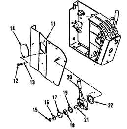
7.
Remove panel (11, Figure 13-53).
8.
Remove two bolts (12), washers (13) and
plate (14).
9.
Remove nut (15), washer (16), seat (17),
spring (18), washer (19), lever (20), bearing
(21) and disc (22).
Figure 13-52.
Figure 13-53.
Go to Sheet 3
13-56