TM 5-3805-261-20
ELECTRICAL SYSTEM. (cont)
7-9.
Starting System STE/ICE Tests. (cont)
g.
TEST 89. 0-45 VOLTS (cont)
2.
Negative Voltage Drop
(a)
MASTER DISCONNECT SWITCH
(1)
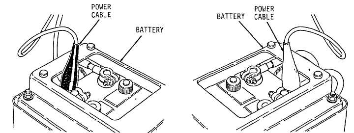
Refer to VTM-General Setup and Checkout Instructions in TM 9-4910-571-12 & P. Connect a
power cable to battery (Figure 6-4).
Figure 6-4.
(2)
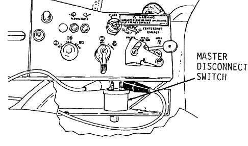
Remove cover to operator panel on right side of seat to expose master disconnect switch.
(3)
Attach red lead clip and black lead clip across switch (Figure 7-17).
Figure 7-17.
7-34