TM 5-3805-261-20
SCARIFIER ASSEMBLY MAINTENANCE. (cont)
17-13.
Scarifier Actuating Assembly. (Sheet 2 of 9)
REMOVAL
NOTE
The
following
is
a
maintenance
procedure
for
the
right
scarifier
actuating
assembly.
The
maintenance procedure for the left
scarifier
actuating
assembly
is
identical.
1.
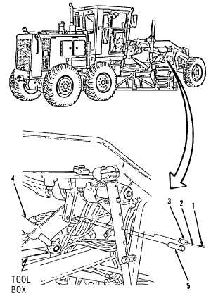
Remove two bolts (1), washers (2) and lock
(3, Figure 17-52).
NOTE
Step 2 requires two mechanics.
2.
One mechanic supports scarifier actuating
assembly
hydraulic
cylinder
(4)
while
second mechanic drives out pin (5).
3.
Set free end of scarifier actuating assembly
hydraulic cylinder (4) down on drawbar
frame tool box.
4.
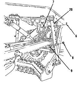
Remove pin assembly (6) and pin (7) from
right side sleeve (20, Figure 17-53).
5.
Remove nut (8) and bolt (9).
Figure 17-52.
Figure 17-53.
Go to Sheet 3
17-42


