TM 5-3805-261-20
HYDRAULIC SYSTEM MAINTENANCE.
15-19.
Hydraulic Control Levers. (Sheet 9 of 11)
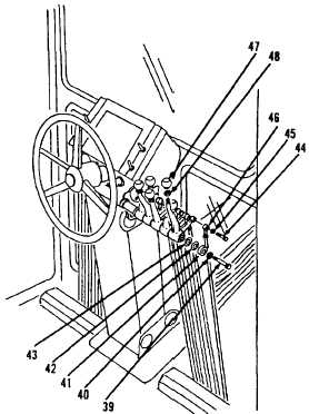
INSTALLATION
19.
Install nut (48) and scarifier knob (47,
Figure 15-41).
20.
Connect linkage (46).
21.
Install lockwasher (45) and bolt (44).
22.
Install bearing (43), shim (42), retainer (41),
washer (40) and bolt (39).
23.
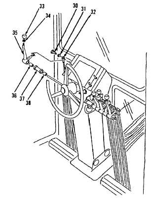
Install bearing (38), spacer (37), bearing
(36) and lever (35, Figure 15-40) on left
side of steering console.
24.
Install nut (34) and blade tip knob (33).
25.
Connect linkage (32).
26.
Install lockwasher (31) and bolt (30).
Figure 15-41.
Figure 15-40.
Go to Sheet 10
15-81


