TM 5-3805-261-10
SECTIONALIZATION FOR AIR TRANSPORT - CONTINUED
0019 00
ASSEMBLY - CONTINUED
NOTE
The holes in the sides of the pivot pin cap must face the sides of the machine for mounting the pump drive-
shaft guard, and the grease fitting must face the right side.
36.
Install upper pivot pin (9), four washers (11), and bolts (10). Gradually tighten bolts in a diagonal pattern. Tighten bolts
to 75 lb-ft (100 Nm).
6
10,11
9
397-1067
37.
Turn off the battery disconnect switch.
38.
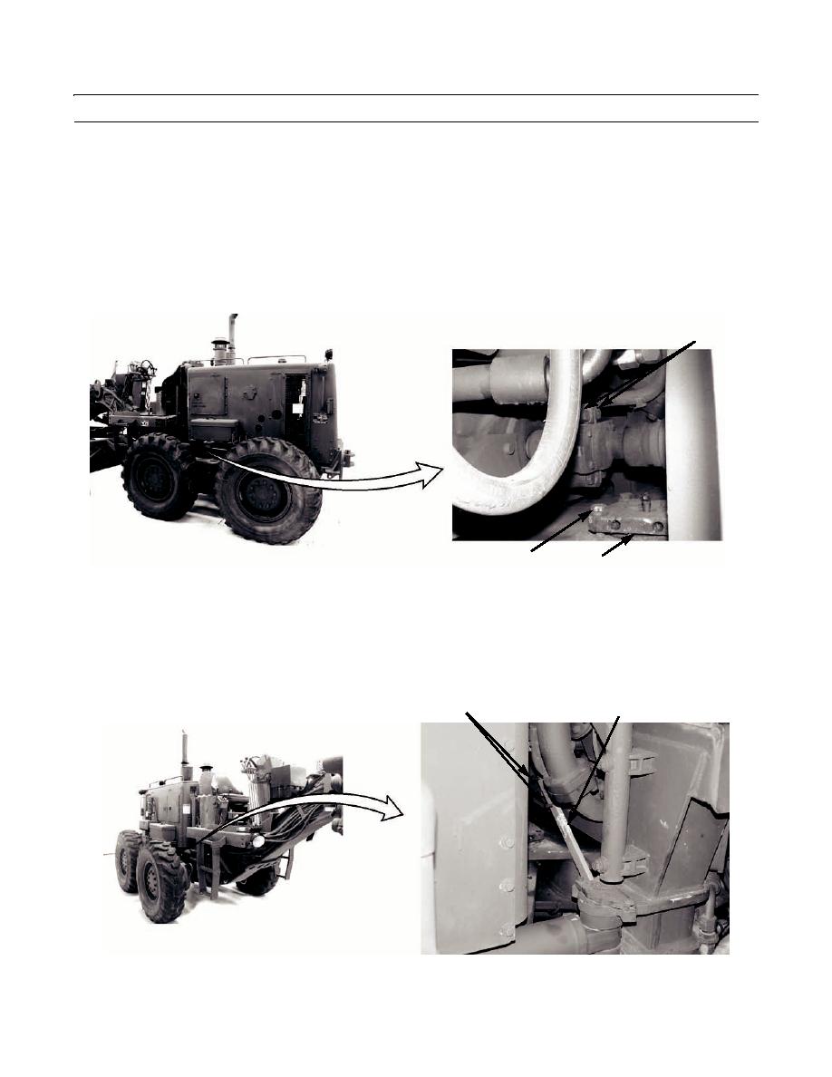
Remove the engine drive yoke guard from the fire wall and store in the tool box.
39.
Remove two bolts (6) and pump driveshaft lock bar from the yoke. Store lock bar in front tool box.
6
LOCK BAR
397-1100
0019 00-29


