
TM 5-3805-293-23-5
0302
REMOVAL CONTINUED
9. Start machine and retract centershift cylinder (TM 5-3805-293-10).
10. Shut off machine (TM 5-3805-293-10).
11. Install vacuum cap (WP 0221).
12. Release centershift circuit pressure (WP 0218).
WARN I N G
Hydraulic oil is very slippery. Immediately wipe up any spills. Failure to follow this warning
may cause injury to personnel.
N OT E
Tag and mark hoses to aid in installation.
Cap all open lines and fittings to prevent dirt from entering system and to prevent leakage.
Keep all parts clean from contaminants. Contaminants may cause rapid wear and
shortened component life.
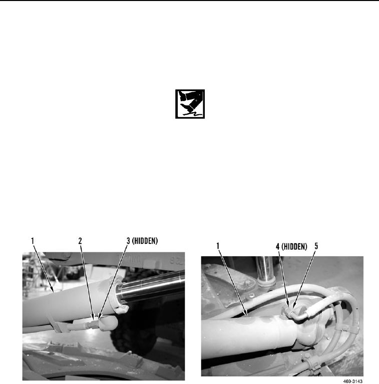
13. Disconnect hydraulic hoses (Figure 5, Items 2 and 5) and remove two O-rings (Figure 5, Items 3 and 4) from
centershift cylinder (Figure 5, Item 1). Discard O-rings.
Figure 5. Upper and Lower Hydraulic Hoses.
0302