
TM 5-3805-293-23-5
0301
INSTALLATION CONTINUED
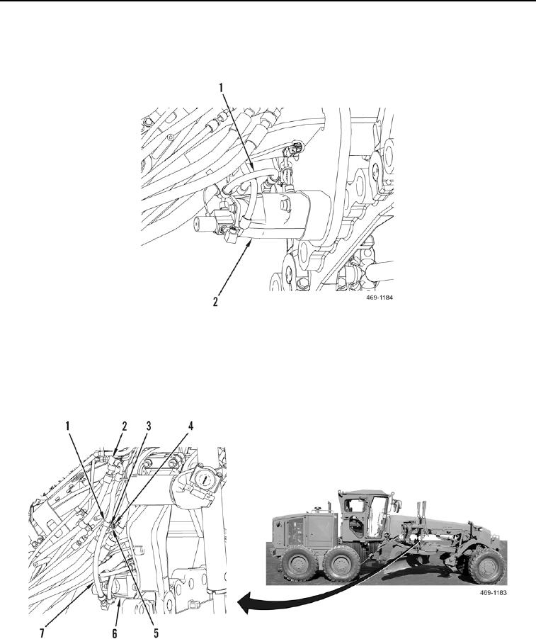
5. Install hydraulic hose (Figure 5, Item 1) on centershift lock (Figure 5, Item 2).
6. Connect hydraulic hose (Figure 5, Item 1) to centershift lock (Figure 5, Item 2).
Figure 5. Hydraulic Hose 2.
0301
7. Install spacer (Figure 6, Item 4), clamp (Figure 6, Item 1), hydraulic hose (Figure 6, Item 7), washer (Figure 6,
Item 3), and nut (Figure 6, Item 5) on machine.
8. Connect hydraulic hose (Figure 6, Item 7) to tee (Figure 6, Item 2).
9. Connect hydraulic hose (Figure 6, Item 7) to centershift lock (Figure 6, Item 6).
Figure 6. Hydraulic Hose 1.
0301
END OF TASK